Most embedded systems use more than one power cable, many using four or more. A single IC, such as an FPGA, DSP, or microcontroller, may have specific timing requirements. For example, a chip manufacturer may recommend that the I/O supply voltage be applied after the core voltage supply has stabilized. Another manufacturer may require that power should be supplied within a relatively specified time in order to avoid prolonged voltage differences across the supply pins. The power-up sequence between the processor and external memory may also be critical.
The chip manufacturer may specify that certain power supplies must be started in a single sequential manner to avoid multiple power-on resets. This can be challenging because inrush currents can place very high transient demands on the point-of-load regulator. In this case, the starting shape of the power cord is as important as the timing sequence.
Once you combine the various power requirements of the chip, the overall power supply, the reference power supply, and other IC point-of-load regulators, you will soon encounter 78 power lines.
Using a 4-channel oscilloscope to verify power line timing in an embedded system can be time consuming, but this is what most engineers must do. When we communicate with oscilloscope users, evaluating the power-on sequence and shutdown sequence is one of the most common reasons engineers want more than four channels. In this article, we will briefly describe the use of a 4-channel oscilloscope to evaluate the power-on sequence and shutdown sequence, and demonstrate the use of some examples of 8-channel oscilloscopes.
One of the methods of the traditional 4-channel oscilloscope method is to analyze the power system in a module-by-module manner. That is, multiple acquisitions are used and the timing is checked one by one. To compare different modules, you can use one of the power-up traces or the Power Good/Fail signal as a trigger. You can perform multiple captures to determine the startup and shutdown times relative to the reference signal. Due to the acquisition in multiple power cycles, it is difficult to characterize the relative timing offset of the power supply. However, by using the infinite persistence function on the oscilloscope, it is possible to determine the variation range of each power supply in different cycles over multiple power cycles.
Another common method is to "cascade" multiple oscilloscopes, usually by triggering the oscilloscope on one of the power supplies or on the common Power Good/Fail signal.
Both methods are time-consuming and require special attention to synchronization:
• Be careful when dealing with synchronization and time uncertainty • You can pool data, develop system timing diagrams, but it takes a long time • Complexity increases with the number of observed power tracks • Settings must be perfectly uniform • Must be provided using one measurement channel Simultaneous use of MSO extensions The number of mixed signal oscilloscopes provides more channels for power sequencing. To do this, the MSO must have a suitable voltage range on the digital input and can independently adjust the threshold. For example, the Tektronix MDO4000C with the MSO option provides 16 digital inputs, each with an independent threshold, up to 200 MHz supporting ± 30 Vp-p dynamic range, and is suitable for most voltage levels in a typical design. Note If your goal is to strictly measure the timing relationship, this is especially suitable for this method, but you cannot measure the rise/fall time or shape (monotonicity) of the power on/off.
An 8-channel oscilloscope speeds up processing Compared to all previous methods, using an oscilloscope with eight analog channels can significantly reduce time and reduce clutter. In an 8-channel oscilloscope, analog probes can be used to characterize up to 8 power cables. To measure the start and shutdown timing of more than 8 power cables, you can also use a mixed signal oscilloscope with digital signal input and independently adjustable thresholds.
Now let's look at some typical power sequencing applications.
Power on delay with remote on/off
The switching power supply under test in the screenshot below generates a high-current, regulated 12 VDC output. This power is remotely controlled via the switch on the front panel of the instrument. Shortly after the switch is pressed, the +5 V standby power is turned on and the switching converter starts. After the +12 V output is stable, the Power Good (PW OK) signal goes high, indicating that the supply is reliable.
The +5 V standby voltage signal provides a simple rising edge trigger for the relevant signal acquisition. The automatic measurement function verifies that the output voltage start delay is <100 ms, and the delay from the start of the output voltage to PW OK is within the specification range of 100 – 500 ms.
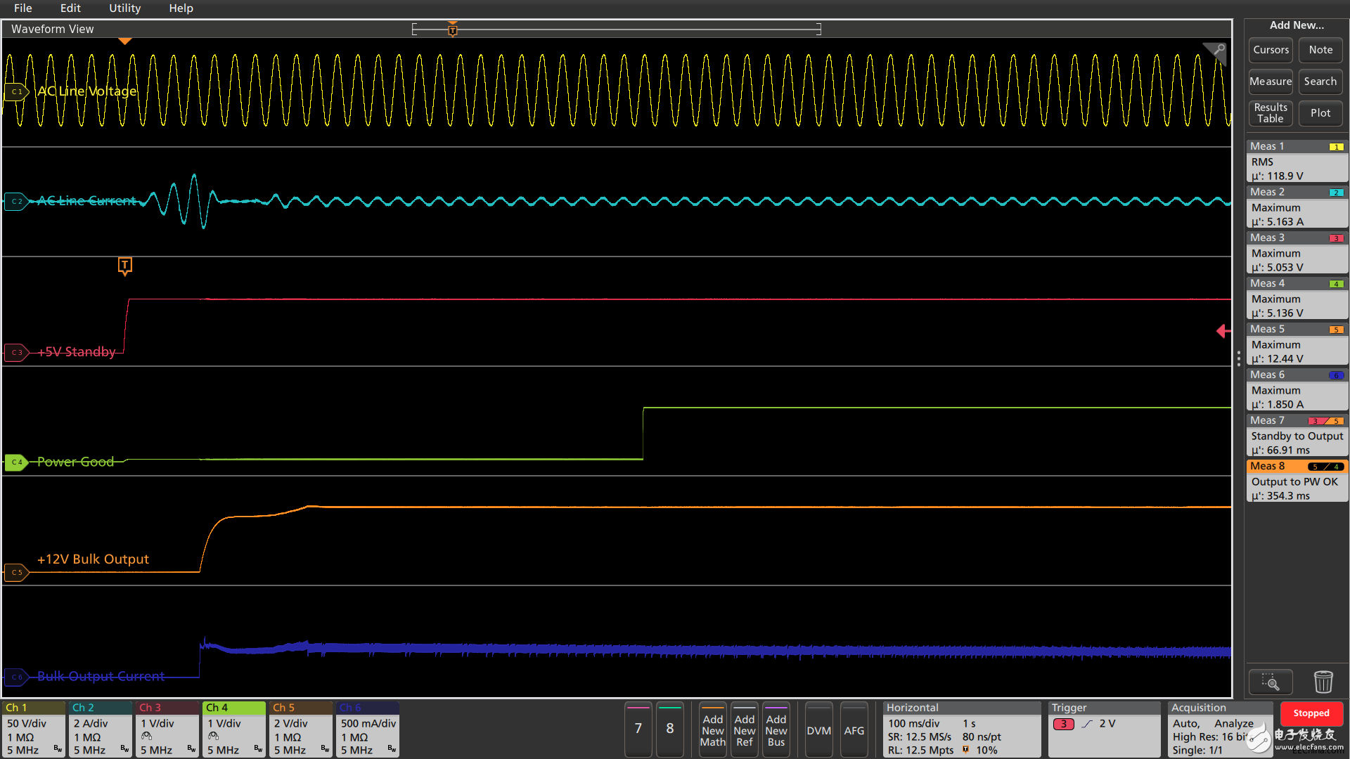
This screenshot shows the measurement of AC/DC switching power supply startup after pressing the front panel switch.
Shutdown delay with remote ON/OFF After the main power switch is turned off, the switching converter is turned off and the output voltage is reduced. According to the specification, the power supply must be kept at least 20 ms after the switch is pressed. Most importantly, according to the specification, before the +12 V output voltage falls outside of the regulation range, the PW OK signal is decremented by 5 – 7 ms, allowing the load time to react and shut down cleanly.
As shown in the figure below, the PW OK signal provides a falling edge trigger for the acquisition of the relevant signal. Waveform Cursor Measurement Verify that the PW OK warning signal works in a satisfactory manner.
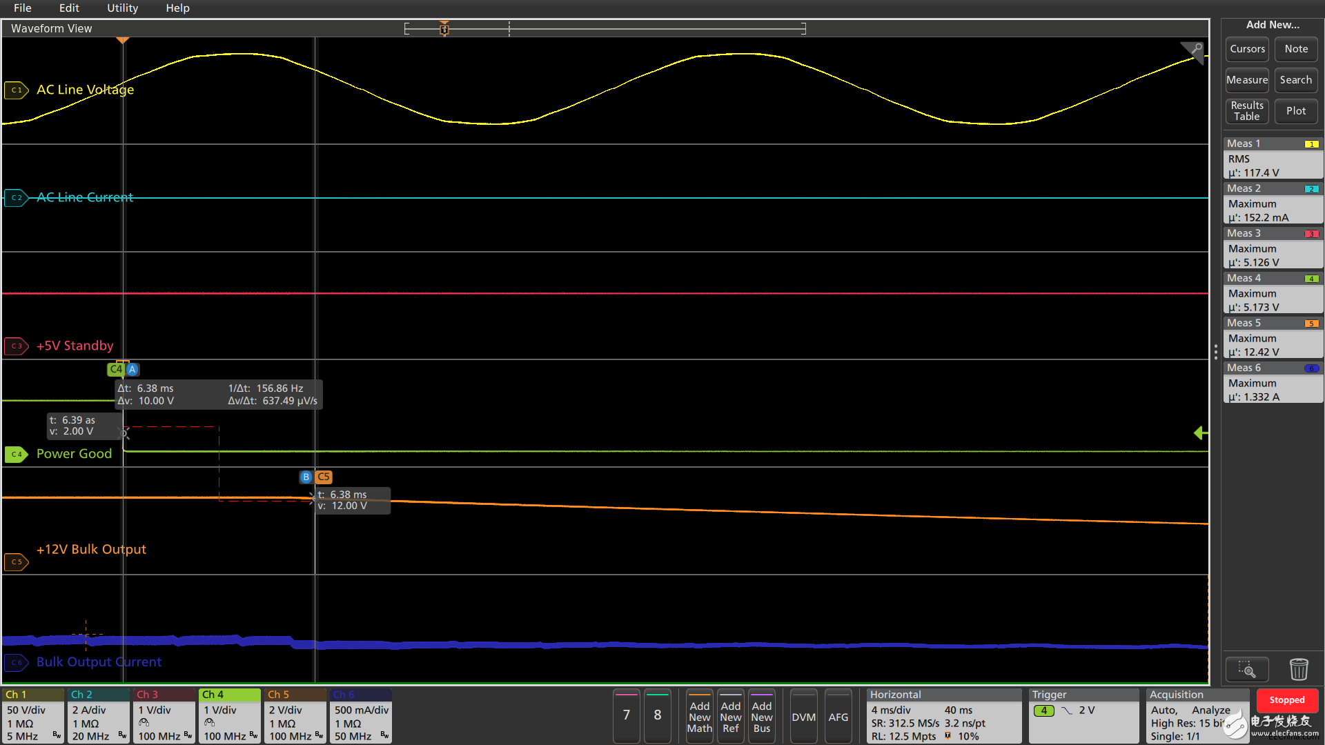
You can use waveform cursor measurements to verify that the PW OK warning signal works in a manner that meets specifications.
Check the timing in multiple power cycles
To verify that the power-on timing is within the specification range for multiple power cycles, infinite persistence can be used, the timing of the display signal changes, and the automatic timing measurement statistic screen will quantify the deviation. In the settings shown below, 50% of the +5V standby voltage is used as the timing reference. The boot sequence is repeated 10 times. The timing deviation in 10 boot cycles is slightly higher than 1%.
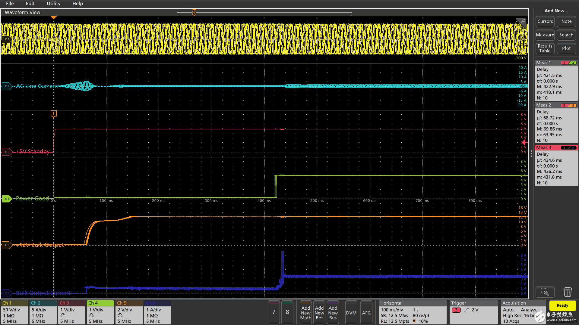
Infinite persistence and measurement statistics can be used to achieve repeated start timing measurements.
Load point regulated power supply timing The following screenshot shows the turn-on time of a system board's power supply at seven load points during power-up. The input power to the board is the +5V standby signal in the above example and the +12 VDC overall voltage.
The automatic power-on delay measurement in this test is performed between the 50% points automatically calculated for each waveform, so each measurement has a different configuration and a different set of measurement thresholds. The first measurement shows the delay from the +5 V standby signal to the overall +12 V supply, and the second measurement is the +5 V supply delay. The remaining measurements are the key delay sequences for the mains +5 V supply.
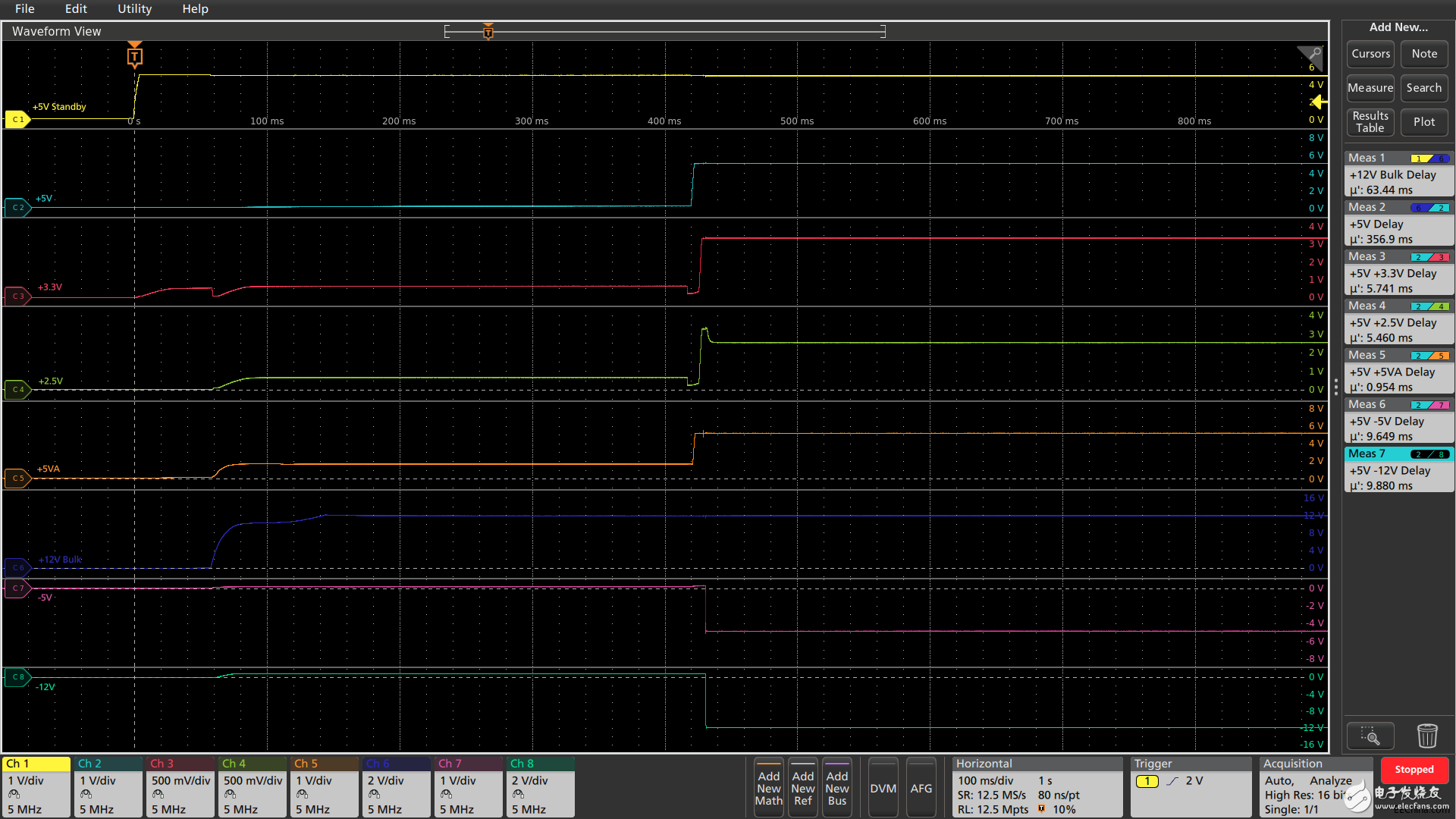
This measurement shows the start timing of seven regulated power supplies.
Shutdown timing of regulated power supply The automatic shutdown delay measurement in this test is performed between each waveform point that is less than 5% of the nominal value. Unlike the previous percentage-based measurement threshold, each measurement has an absolute voltage threshold. The Power Good signal drops when the power is turned off. As shown in the screenshot below, some power loads are heavier and the shutdown is faster.
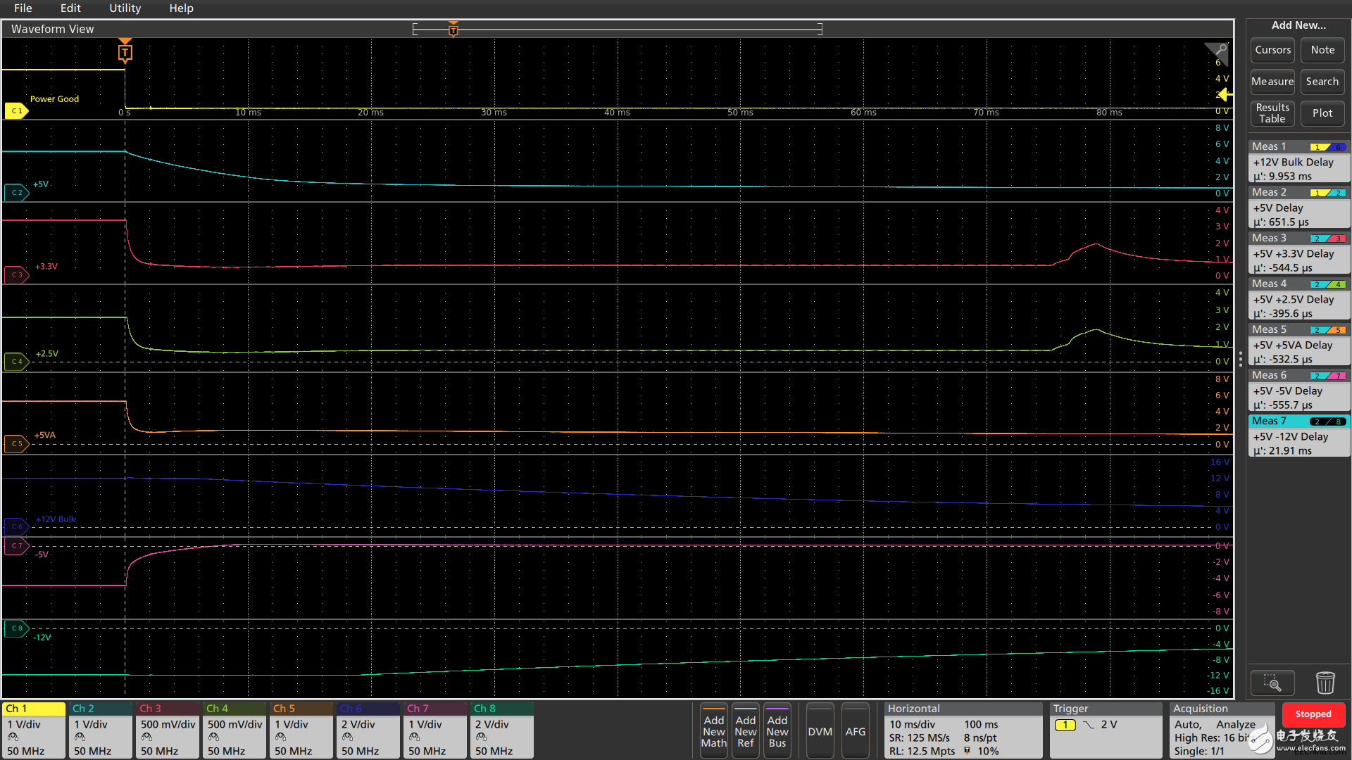
As can be seen from the figure, part of the power load is heavier and the shutdown is faster.
Auto-offset timing for more than 8 tracks is measured based on the time the signal crosses its respective threshold voltage. Since each automatic measurement configuration will include a unique threshold (usually 50% of the signal amplitude), each digital channel may have a unique threshold (usually set to 50% of the supply voltage), so a mixed signal oscilloscope can perform the following Power delay measurements are shown until the number of available digital inputs. According to the MSO model, the number of channels can be between 8~64.
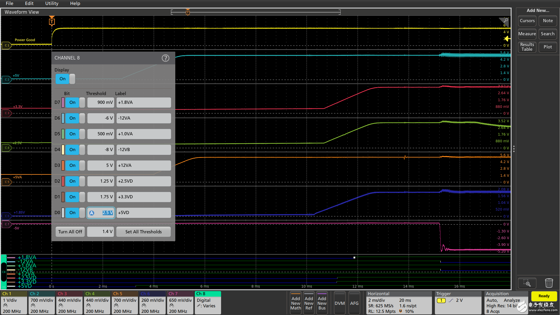
This shows the use of digital channels to check the start timing of more than 8 regulated power supplies.
Power rise time measurement In addition to the power supply sequencing, the rise time of the power supply must be controlled to meet the specifications of some key components in the system. Automatic rise and fall time measurements are also based on voltage reference points. By default, voltage reference points are automatically calculated to be 10% and 90% of the signal amplitude of each channel. In the simple example shown below, the result box in the right side of the display shows the rise time of the positive power supply and the fall time of the negative power supply.
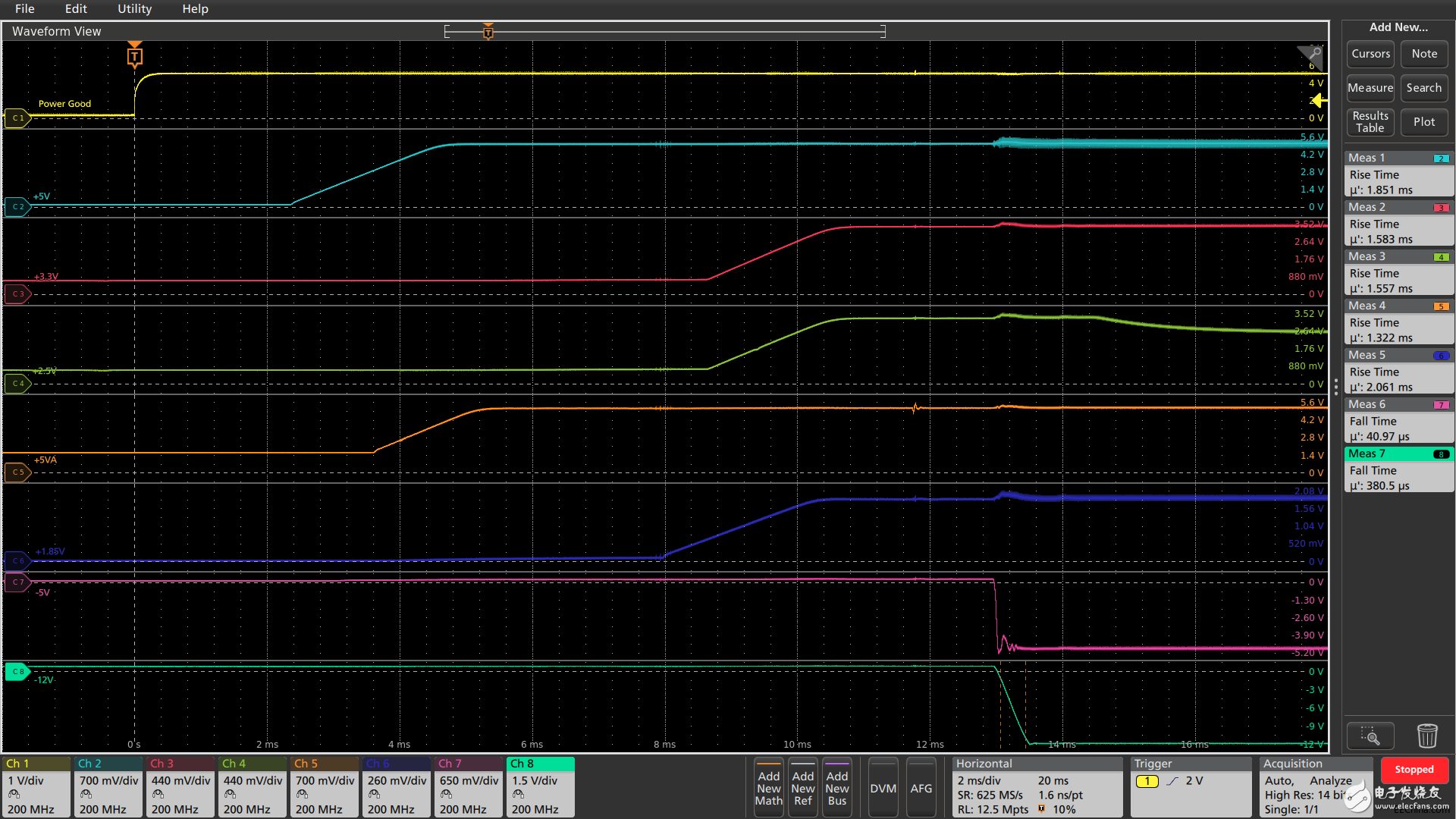
The screenshot shows that the rising and falling time measurements are displayed in the results box on the right side of the screen.
About the Author:
Dave Pereles is currently the Technical Marketing Manager of Tektronix Technology. He has worked in the test and measurement industry for more than 25 years and has held various positions such as application engineer and product manager. He graduated with a Bachelor of Science degree in electrical engineering from Trinity College, Hartford, Connecticut, USA, and graduated from Seattle University with an MBA.
The chip manufacturer may specify that certain power supplies must be started in a single sequential manner to avoid multiple power-on resets. This can be challenging because inrush currents can place very high transient demands on the point-of-load regulator. In this case, the starting shape of the power cord is as important as the timing sequence.
Once you combine the various power requirements of the chip, the overall power supply, the reference power supply, and other IC point-of-load regulators, you will soon encounter 78 power lines.
Using a 4-channel oscilloscope to verify power line timing in an embedded system can be time consuming, but this is what most engineers must do. When we communicate with oscilloscope users, evaluating the power-on sequence and shutdown sequence is one of the most common reasons engineers want more than four channels. In this article, we will briefly describe the use of a 4-channel oscilloscope to evaluate the power-on sequence and shutdown sequence, and demonstrate the use of some examples of 8-channel oscilloscopes.
One of the methods of the traditional 4-channel oscilloscope method is to analyze the power system in a module-by-module manner. That is, multiple acquisitions are used and the timing is checked one by one. To compare different modules, you can use one of the power-up traces or the Power Good/Fail signal as a trigger. You can perform multiple captures to determine the startup and shutdown times relative to the reference signal. Due to the acquisition in multiple power cycles, it is difficult to characterize the relative timing offset of the power supply. However, by using the infinite persistence function on the oscilloscope, it is possible to determine the variation range of each power supply in different cycles over multiple power cycles.
Another common method is to "cascade" multiple oscilloscopes, usually by triggering the oscilloscope on one of the power supplies or on the common Power Good/Fail signal.
Both methods are time-consuming and require special attention to synchronization:
• Be careful when dealing with synchronization and time uncertainty • You can pool data, develop system timing diagrams, but it takes a long time • Complexity increases with the number of observed power tracks • Settings must be perfectly uniform • Must be provided using one measurement channel Simultaneous use of MSO extensions The number of mixed signal oscilloscopes provides more channels for power sequencing. To do this, the MSO must have a suitable voltage range on the digital input and can independently adjust the threshold. For example, the Tektronix MDO4000C with the MSO option provides 16 digital inputs, each with an independent threshold, up to 200 MHz supporting ± 30 Vp-p dynamic range, and is suitable for most voltage levels in a typical design. Note If your goal is to strictly measure the timing relationship, this is especially suitable for this method, but you cannot measure the rise/fall time or shape (monotonicity) of the power on/off.
An 8-channel oscilloscope speeds up processing Compared to all previous methods, using an oscilloscope with eight analog channels can significantly reduce time and reduce clutter. In an 8-channel oscilloscope, analog probes can be used to characterize up to 8 power cables. To measure the start and shutdown timing of more than 8 power cables, you can also use a mixed signal oscilloscope with digital signal input and independently adjustable thresholds.
Now let's look at some typical power sequencing applications.
Power on delay with remote on/off
The switching power supply under test in the screenshot below generates a high-current, regulated 12 VDC output. This power is remotely controlled via the switch on the front panel of the instrument. Shortly after the switch is pressed, the +5 V standby power is turned on and the switching converter starts. After the +12 V output is stable, the Power Good (PW OK) signal goes high, indicating that the supply is reliable.
The +5 V standby voltage signal provides a simple rising edge trigger for the relevant signal acquisition. The automatic measurement function verifies that the output voltage start delay is <100 ms, and the delay from the start of the output voltage to PW OK is within the specification range of 100 – 500 ms.

This screenshot shows the measurement of AC/DC switching power supply startup after pressing the front panel switch.
Shutdown delay with remote ON/OFF After the main power switch is turned off, the switching converter is turned off and the output voltage is reduced. According to the specification, the power supply must be kept at least 20 ms after the switch is pressed. Most importantly, according to the specification, before the +12 V output voltage falls outside of the regulation range, the PW OK signal is decremented by 5 – 7 ms, allowing the load time to react and shut down cleanly.
As shown in the figure below, the PW OK signal provides a falling edge trigger for the acquisition of the relevant signal. Waveform Cursor Measurement Verify that the PW OK warning signal works in a satisfactory manner.

You can use waveform cursor measurements to verify that the PW OK warning signal works in a manner that meets specifications.
Check the timing in multiple power cycles
To verify that the power-on timing is within the specification range for multiple power cycles, infinite persistence can be used, the timing of the display signal changes, and the automatic timing measurement statistic screen will quantify the deviation. In the settings shown below, 50% of the +5V standby voltage is used as the timing reference. The boot sequence is repeated 10 times. The timing deviation in 10 boot cycles is slightly higher than 1%.

Infinite persistence and measurement statistics can be used to achieve repeated start timing measurements.
Load point regulated power supply timing The following screenshot shows the turn-on time of a system board's power supply at seven load points during power-up. The input power to the board is the +5V standby signal in the above example and the +12 VDC overall voltage.
The automatic power-on delay measurement in this test is performed between the 50% points automatically calculated for each waveform, so each measurement has a different configuration and a different set of measurement thresholds. The first measurement shows the delay from the +5 V standby signal to the overall +12 V supply, and the second measurement is the +5 V supply delay. The remaining measurements are the key delay sequences for the mains +5 V supply.

This measurement shows the start timing of seven regulated power supplies.
Shutdown timing of regulated power supply The automatic shutdown delay measurement in this test is performed between each waveform point that is less than 5% of the nominal value. Unlike the previous percentage-based measurement threshold, each measurement has an absolute voltage threshold. The Power Good signal drops when the power is turned off. As shown in the screenshot below, some power loads are heavier and the shutdown is faster.

As can be seen from the figure, part of the power load is heavier and the shutdown is faster.
Auto-offset timing for more than 8 tracks is measured based on the time the signal crosses its respective threshold voltage. Since each automatic measurement configuration will include a unique threshold (usually 50% of the signal amplitude), each digital channel may have a unique threshold (usually set to 50% of the supply voltage), so a mixed signal oscilloscope can perform the following Power delay measurements are shown until the number of available digital inputs. According to the MSO model, the number of channels can be between 8~64.

This shows the use of digital channels to check the start timing of more than 8 regulated power supplies.
Power rise time measurement In addition to the power supply sequencing, the rise time of the power supply must be controlled to meet the specifications of some key components in the system. Automatic rise and fall time measurements are also based on voltage reference points. By default, voltage reference points are automatically calculated to be 10% and 90% of the signal amplitude of each channel. In the simple example shown below, the result box in the right side of the display shows the rise time of the positive power supply and the fall time of the negative power supply.

The screenshot shows that the rising and falling time measurements are displayed in the results box on the right side of the screen.
About the Author:
Dave Pereles is currently the Technical Marketing Manager of Tektronix Technology. He has worked in the test and measurement industry for more than 25 years and has held various positions such as application engineer and product manager. He graduated with a Bachelor of Science degree in electrical engineering from Trinity College, Hartford, Connecticut, USA, and graduated from Seattle University with an MBA.
The replacement bulb lamp is a substitute bulb for the projector. The price of the replacement bulb lamp will be more affordable than the original Projector Lamp, and the average life can reach 3000 hours, which is suitable for basic film and television in daily life. The operation is simple and easy to install.
Replacement Bulb Lamp,Projector Bulb,Replacement Original Bulb Lamp,Projector Bulb Lamp
Shenzhen Happybate Trading Co.,LTD , https://www.happybateprojector.com