Conversion principle and parameter indicators
1. Sampling Theorem
2. In order to correctly and correctly use the sampled signal vs as shown in Figure 5.2.2 to represent the analog signal vi , it must be satisfied that fs>=2fmax
Fs is the sampling frequency ; fmax is the frequency of the highest frequency component of the input signal vi ; the above equation is the so-called sampling theorem. Under the condition that the sampling theorem is satisfied, the signal vs can be reduced to vi by a low-pass filter. The voltage transmission coefficient |A(f)| of the low-pass filter should remain unchanged in the range below fmax , and in fs -fmax should be rapidly reduced to zero before, and the sampling theorem specifies the lower frequency limit of the A/D conversion.
Problems encountered with AD7792 / knowledge points learned
Knowledge points learned:
1. In the stm32
U8 : unsigned char
U16 : unsigned short
U32 : unsigned int
2. In the stm32 , the voltage value sampled by AD7792 is converted into ASCII characters and printed in the serial port. There are two programming methods:
u8TempD;
U16 Datau16;
Char str[20];
Unsigned short iData[3];
U8 Strvbat[8]={'/','/','/',',',0,0,0,0};
U8 ASCII[21]={'0','1','2','3','4','5','6','7','8','9','A' , 'B', 'C', 'D', 'E', 'F', '+', //10->16
',',//11-17
'-', // 12-18
'.', // 13-19
'/', // 14-20
};
Method 1: (simple version)
AD_VBat[TempD] = SPI_Read16Bit();
Memcpy(&iData[0],& AD_VBat[TempD],2);
Sprintf(str,"%d",iData[0]);
UART1_TX485_Puts(USART1,&str[0]);
Method 2: (complex version)
AD_VBat[TempD] = SPI_Read16Bit();
Datau16 = AD_VBat[TempD];
Strvbat[0]=ASCII[Datau16/10000];
Strvbat[1]=ASCII[Datau16%10000/1000];
Strvbat[2]=ASCII[Datau16%1000/100];
Strvbat[3]=ASCII[Datau16%100/10];
Strvbat[4]=ASCII[Datau16%10];
UART1_TX485_Puts(USART1,&Strvbat[0]);
While(USART_GetFlagStatus(USART1, USART_FLAG_TXE)==RESET);
3. Problems encountered
Problem 1: Through the serial port printing, the sampled value is about 32768. The converted battery voltage is 2.5V, and the actual battery voltage should be 3.32v. The sample value should be about 43582 .
The root cause of the problem : the problem of channel switching;
The AD7792 has three analog input channels, initialize the AD7792 configuration function, write the configuration register SPI_SendByte (0x10); /* write the configuration register */
SPI_Send16Bit(0x1080); // Offset voltage disable disable fuse current unipolar coded internal reference
The sampling channel set by SPI_Send16Bit (0x1080) is the channel for sampling current, so the value of current is sampled;
Question 2: When the transplanted AD7792 is isolated, it is found that the battery voltage sample value is printed as 0000;
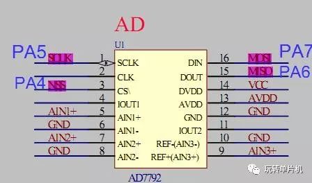
Root cause of the problem: SPI configuration problem;
Schematic:

Misconfiguration:
GPIO_InitStructure.GPIO_Pin = GPIO_Pin_5 | GPIO_Pin_7 ;
GPIO_InitStructure.GPIO_Mode = GPIO_Mode_AF_PP; // Multiple push-pull output
GPIO_InitStructure.GPIO_Speed ​​= GPIO_Speed_50MHz;
GPIO_Init(GPIOA, &GPIO_InitStructure);
             Â
GPIO_InitStructure.GPIO_Pin = GPIO_Pin_6;
GPIO_InitStructure.GPIO_Speed ​​= GPIO_Speed_50MHz;
GPIO_InitStructure.GPIO_Mode = GPIO_Mode_IN_FLOATING; //Floating input
GPIO_Init(GPIOA, &GPIO_InitStructure);
GPIO_InitStructure.GPIO_Pin = GPIO_Pin_4;
GPIO_InitStructure.GPIO_Speed ​​= GPIO_Speed_50MHz;
GPIO_InitStructure.GPIO_Mode = GPIO_Mode_Out_PP; // Universal push-pull output
GPIO_Init(GPIOA, &GPIO_InitStructure);
Correct configuration:
/* Configure SPI1 pins: SCK, MISO and MOSI */
GPIO_InitStructure.GPIO_Pin = GPIO_Pin_5 | GPIO_Pin_4|GPIO_Pin_7;
GPIO_InitStructure.GPIO_Mode = GPIO_Mode_Out_PP; //Universal push-pull output
GPIO_InitStructure.GPIO_Speed ​​= GPIO_Speed_50MHz;
GPIO_Init(GPIOA, &GPIO_InitStructure);
Â
/* Configure MISO as input */
GPIO_InitStructure.GPIO_Pin = GPIO_Pin_6;
GPIO_InitStructure.GPIO_Speed ​​= GPIO_Speed_50MHz;
GPIO_InitStructure.GPIO_Mode = GPIO_Mode_IN_FLOATING; //Floating input
GPIO_Init(GPIOA, &GPIO_InitStructure);
Immersion Cooling is a technique used to cool components of IT equipment that consists of submerging the computer components in a thermally conductive and dielectric liquid. Through this practice, the servers are cooled and heat is transferred from the source to the liquid.
When we talk about Immersion Cooling, we also need to discuss the different types of Immersion Cooling, as well as the applications of Immersion cooling. The practice of Immersion Cooling has a multitude of benefits particularly as it allows datacenters to be managed in a greener and more sustainable manner. Environmental concerns has been a huge catalyst for the adoption of the technology in recent years.
deionized water
mineral oil
fluorocarbon-based fluids
synthetic
Immersion Cooling systems used to have a higher fluid cost than water cooling, but this is already changing.
A wide variety of liquids exist for this purpose, the most suitable being transformer oils and other electrical cooling oils. Non-purpose oils, including cooking, motor and silicone oils, have been successfully used for cooling personal computers
water cooling,oil cooling,immersion cooling box,liquid immersion cooling,apw12 power supply
Shenzhen YLHM Technology Co., Ltd. , https://www.asicminer-ylhm.com