Ripple is the core indicator of power, but how to accurately measure ripple is indeed a widely overlooked problem. Maybe you think that is not the oscilloscope AC coupling, and then point the probe on the power supply? This is far from the truth. This article presents you with the correct way to test the ripple.
Probe selectionMore than a decade ago, many companies had clear regulations on power test standards that required measurements using a 1:1 probe. Because this probe does not lose the measurement position of the oscilloscope, for example, the original minimum position of the oscilloscope is 2mv/div, and the ripple can still be measured through this gear with the 1:1 probe, that is, the ripple within 10mv can be accurately measured. . However, since the bandwidth of this type of probe can only be about 6MHz, this probe is no longer suitable for use as the frequency of the switching power supply increases.
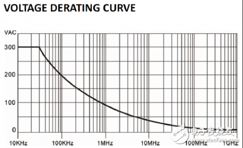
The commonly used power measurement probes are 10:1 passive probes, 100:1 passive probes, and high voltage differential probes. The choice of probe must first consider the voltage range, and the measured voltage should not exceed the allowable range of the probe. For example, a typical 10:1 passive probe has a low-frequency withstand voltage of 300VRMS and decreases with increasing frequency. As shown in Figure 1. The voltage range to be measured before use is within this range. Otherwise, the correct measurement will not be possible.

Figure 1 10:1 passive probe input rated voltage curve
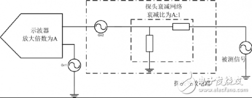
In addition, it is necessary to consider the amplification of the probe attenuation ratio to the noise floor to determine the true and effective part of the signal. The schematic diagram when using the probe measurement is shown in Figure 2, where Gn1 is a virtual noise source, indicating the low noise of the oscilloscope, and Gn2 is the noise floor of the probe. Since the signal is attenuated by the probe, in order to restore the size of the real signal, the oscilloscope will further amplify the signal, and then Gn1 and Gn2 will be amplified, and the amplification factor is the reciprocal of the attenuation ratio. Therefore, the larger the attenuation factor, the more the noise floor of the measurement system is amplified.

Figure 2 bottom noise amplification diagram
For example, using a 500:1 high-voltage differential probe for measurement, the oscilloscope noise floor is 1mv, the probe noise is 1mv, so the accumulated noise is 2mv, and after 500 times amplification, the noise floor reaches 1V. At this point, you need to consider whether the noise of 1V is within the allowable range. If the ripple of your system under test is only 1V or less, the noise of 1V is obviously not allowed.
10Kv Steel Pole,Metal Pole,Metal Pole Barns,Metal Poles For Fence
Jiangsu Baojuhe Science and Technology Co.,Ltd. , https://www.galvanizedsteelpole.com