According to the demand of the piezoelectric ceramic micro-displacement device for the driving power supply, the scheme of the piezoelectric driving power supply system is designed. The scheme first introduces the digital circuit part and the analog circuit part in the power system, and analyzes and improves the accuracy and stability of the driving power supply. Finally, the performance of the driving power supply was experimentally verified. The experimental results show that the power supply output voltage noise of the design scheme is lower than 0.43 mV, the maximum nonlinear error of output is less than 0.024%, and the resolution is up to 1.44 mV, which can meet the requirements of static positioning control in high-resolution micro-displacement positioning system.
The piezoelectric ceramic actuator (PZT) is the core of the micro-displacement platform. Its main principle is to use the inverse piezoelectric effect of the piezoelectric ceramic to generate deformation, thereby driving the actuator to undergo micro-displacement. Piezoelectric ceramic drivers have the advantages of high resolution, fast response frequency, large thrust and small volume, and have been widely used in aerospace, robotics, micro-electromechanical systems, precision machining and bioengineering. However, the application of piezoelectric ceramic drivers is inseparable from the piezoelectric ceramic driving power supply with good performance. To achieve nano-scale positioning applications, the output voltage of a piezoelectric ceramic drive power supply needs to be continuously adjustable within a certain range, and the same voltage resolution needs to reach millivolts. Therefore, piezoelectric ceramic drive power technology has become a key technology in piezoelectric micro-displacement platforms.
D/A circuit design
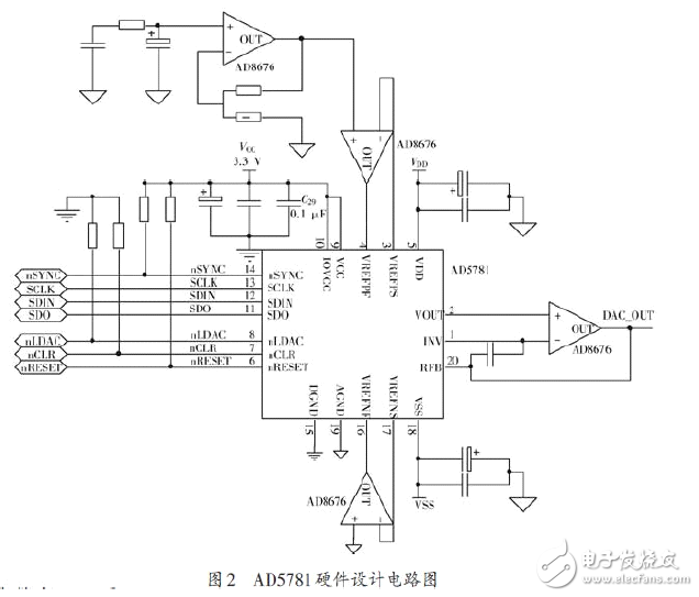
Since the piezoelectric driver requires an output voltage range of 0 to 100 V and a resolution of millivolts, the resolution of the D/A needs to be sub-millivolt. This design uses the AD5781 as a D/A device. The AD5781 is an 18-bit high-precision converter with an SPI interface that provides an output voltage range of -10 to 10 V and provides ±0.5 LSB INL, ±0.5 LSB DNL, ​​and 7.5 nV/Hz noise spectral density. In addition, the AD5781 features extremely low temperature drift (0.05 ppm/°C). Therefore, the D/A converter chip is particularly suitable for the acquisition and control of precision analog data. The D/A circuit design is shown in Figure 2.

In the hardware circuit design, due to the precision architecture adopted by the AD5781, it is required to force detection to buffer its voltage reference input to ensure the specified linearity. Therefore, the amplifier chosen to buffer the reference input should have low noise, low temperature drift and low input bias current characteristics. Using the AD8676, the AD8676 is an ultra-precision, 36 V, 2.8 nV/Hz dual op amp with 0.6 μV/°C low offset drift and 2 nA input bias current, which provides a precision voltage reference for the AD5781. The C57 and LDAC pin levels of the AD5781 are pulled low through a pull-down resistor to set the AD5781 to the DAC binary register encoding format and the configuration output to be updated on the rising edge of SYNC. In the software design of the ARM side, in addition to properly configuring the relevant registers of the AD5781, the clock phase, clock polarity, and communication mode of the SPI should be properly configured.
Linear amplifier circuit design
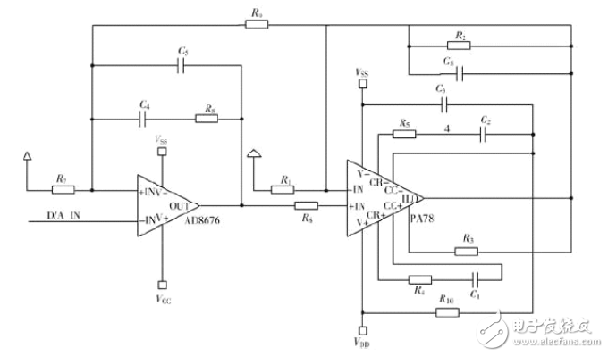
From the engineering point of view, due to the existence of interference sources, the stability of the system will change, resulting in system oscillation. Therefore, the method of ensuring that the control system has certain anti-interference is to make the system have a certain stability margin, that is, a phase angle margin. Due to the stray capacitance in the actual circuit, the capacitance to the ground at the inverting input of the amplifier has a great influence on the stability of the system. As shown in Figure 6, C5 and C6 are used to compensate for the stray capacitance at the opposite end. From the perspective of the system function, it constitutes the lead correction, increases the open-loop cutoff frequency of the open-loop system, and increases the system bandwidth to improve the response speed. The PA78 has two pairs of phase compensation pins that compensate for the internal poles of the amplifier through an external RC network. According to the PA78 data sheet, the poles inside the PA78 are located in the high frequency band. According to the anti-noise ability of the control system, the RC network is configured to rapidly attenuate the amplitude characteristic curve of the high frequency band, thereby improving the anti-interference ability of the system. In the figure, R4, C1 and R5, C2 form an RC compensation network.

In addition, the function of C3 in the circuit is to prevent the interference caused by the vibration of the falling edge of the output signal; R10 acts as a bias resistor to inject the power supply current into the output stage of the amplifier to improve the driving capability of the PA78. Set the PI controller parameters to KP=10 and KI=0.02 respectively; the lead correction compensation capacitors are 12 pF and 220 pF, respectively; the RC compensation network is R=10 kΩ, C=22 pF. Using the Spice model of the linear amplifier circuit Simulation results show that the amplitude-frequency characteristics and the phase-frequency characteristics are as shown. As can be seen from the figure, the amplification system has a bandwidth of up to 100 kHz, which ensures good dynamic characteristics of the system, while the phase angle margin 6 makes the system highly stable.
Our latest USB Type-C socket offers optional splash protection (IPX4 level) and valuable circuit board design space.
Our latest USB Type-C socket protects equipment in harsh environments. It has the industry-leading IPX8 waterproof performance and meets the IEC60529 standard.
China leading manufacturers and suppliers of 5P Through Hole Type,USB Through Hole Type, and we are specialize in MICRO USB Straddle B Type,, etc.
5P Through Hole Type,USB Through Hole Type,MICRO USB Straddle B Type
ShenZhen Antenk Electronics Co,Ltd , https://www.antenkcon.com