Vehicular Ad Hoc Networks (VANET) is a dynamic network composed of WAVE (Wireless Access in Vehicular Environments, WAVE) communications equipment, vehicles, and roadside infrastructure through self-organizing wireless communications. As an important part of the Intelligent Transport System (ITS), VANET plays an important role in traffic safety early warning, urban traffic monitoring, and in-car entertainment.
Because the vehicle-to-vehicle (V2V) communication distance is limited and the vehicle speed is relatively fast, the network topology changes rapidly, but the vehicle can only be driven on the existing road, and the movement state has a certain limit [3]. In view of these characteristics, the strategy of clustering vehicles is an important method to increase vehicle communication time and improve communication success rate [4]. The literature [5] proposed a bus network routing method using bus as the cluster head. This method makes full use of the particularity of the bus and has good delivery performance. The disadvantage is that it is difficult to form a cluster structure on the roads without buses. Literature [3] proposed a vehicle clustering method based on motion consistency. This method takes into account the relative speed of the vehicle and the estimated distance traveled on the current road. The complexity is low, and the communication time of the vehicle is effectively extended.
The clustering of vehicles on the road has increased the success rate of vehicle communications to a certain extent. However, the rapid movement of vehicles has caused problems such as channel instability and frequent network connection interruptions, which still make it difficult to meet the requirements for inter-vehicle communication quality. KHLASS A et al. pointed out that when the channel of a vehicle and a Rode Side Unit (RSU) deteriorates, relaying can be used to improve the communication quality, but the interruption performance is not specifically analyzed [6]. [7] studies the performance of Amplify-and-Forward (AF) and Decode-and-Forward (DF) schemes in cooperative relay systems, and the performance of AF schemes under high SNR conditions. Unlike the DF scheme, because the latter regenerates a clean version of the transmitted signal at the relay, in the low signal-to-noise ratio environment, if the relay node decodes errors, it will cause error propagation and the destination node will receive the error information. In recent years, the Hybrid Decode Amplify Forward (HDAF), which takes into account both the advantages of AF and DF, has become a research hotspot. Literature [8] proposed a vehicle power distribution method that uses the HDAF protocol to reduce total energy consumption while minimizing outage probability in multi-source and multi-relay intelligent transportation systems. In [9], in the AF network, a low complexity PPRS (Pre-Power Allocation and Relay Selection) relay selection method is proposed. However, it is limited to the case where the traditional communication network adopts the AF protocol, and HDAF mode is not considered. And application in VANET.
This paper proposes a vehicle clustering method based on cluster stability. This method prefers buses as cluster heads. In the bus-free area, vehicles with the smallest cluster head factor are selected as cluster heads, which not only makes use of the special advantages of buses in the urban environment, but also ensures the stability of the cluster structure. Based on this, for the intra-cluster vehicle cooperation, based on literature [9], a power pre-distribution relay vehicle selection method applied to collaborative vehicle networking was proposed. This method uses the HDAF forwarding protocol to calculate the power allocation factor of the source vehicle and the potential relay vehicle prior to relay selection, with less disruption and lower complexity.
1
Cluster Stable Clustering Method
1.1 System Model
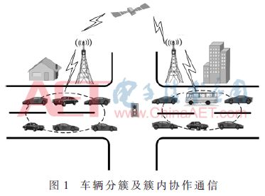
Vehicle clustering and intra-cluster cooperative communication diagram are shown in Figure 1. Assume that each vehicle is equipped with a satellite positioning device that can determine its position, speed, and direction information in real time. Drivers use navigation maps, and vehicles can find out where they are going and where they want to go. Vehicles can exchange information with the surrounding vehicles to calculate the distance from the nearby vehicle [10]. There are a total of N vehicles in the current road section, denoted by ui, i=1,...N. This N vehicle can be divided into M≤N clusters, denoted by Sk, k=1,...,M. Vehicles in the cluster are denoted by uk,j, j=1,...,wk,wk are the number of vehicles in the cluster.
The vehicle information Vinf is defined to include the speed v of the vehicle at the moment, the location of the vehicle at the moment, the expected distance S of the current road, and the distance d from the nearby cluster head. Define the vehicle clustering factor ηk,i:
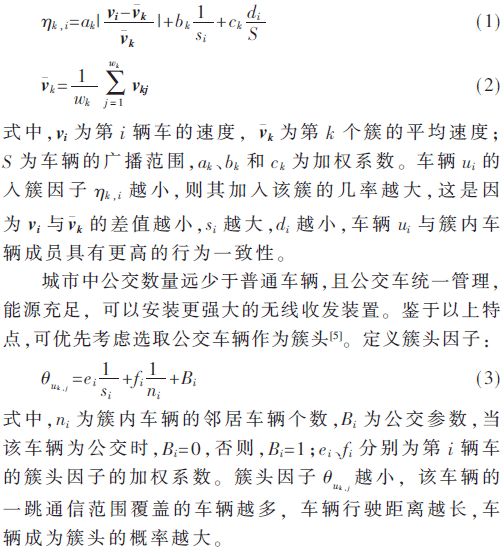
1.2 Clustering method
The vehicle clustering method is divided into two processes, which are cluster generation process and cluster maintenance process. Among other things, the cluster maintenance process includes the processing of cluster vehicles and clustered vehicles outside the cluster.
In the initial stage, the vehicles on the road are isolated nodes. These isolated vehicles obtain their own vehicle information through navigation satellites, including information such as position, speed, and direction. A certain range of N cars is randomly divided into M clusters, respectively Sk, k∈1,..., M. The number of vehicles in the cluster is wk, then the cluster head is selected. The specific process is: if there is no bus in the cluster, the cluster head is selected as the vehicle with the smallest cluster head factor; if there is only one bus in the cluster, the bus is selected as the cluster head If there is more than one bus in the cluster, the bus with the smallest cluster head factor is selected as the cluster head.
Calculate the cluster average speed of each cluster after the vehicle cluster is formed  Compared with kj, if the velocity of the vehicle in the cluster differs from the cluster average velocity too much, the vehicle is removed from the cluster. For out-cluster vehicles, cluster-headed vehicles periodically broadcast cluster head information. Vehicles that do not add any clusters around report their own vehicle information Vinf, calculate their clustering factor, and if the result satisfies the clustering threshold ηth of this cluster, allow the vehicle to join this cluster. Cluster, otherwise it becomes a cluster.
The cluster stabilization method based on clustering is used to improve the reliability of vehicle communication in VANET. This method prefers to use buses as cluster heads. Within a certain range, if there are no buses, the cluster head is selected as the vehicle with the smallest cluster head factor; the key factors d, v, and s during vehicle driving are well considered. Makes the structure of the cluster relatively stable while having less complexity.
2
Intracluster cooperative data distribution
2.1 Collaboration process
In the system shown in FIG. 1, there is one source vehicle Si, one destination vehicle D, and n relay vehicles Ri (i=1,..., N). Among them, the transmission powers of the source vehicle and the relay vehicle are Ps and Pi, respectively, and the relay vehicles participating in cooperative relaying are set as G={1, 2,..., G}. The channels between vehicles are statistically independent and obey frequency flat fading, and vehicle communication works in a half duplex state. The cooperation process is divided into two steps: the first step is the source vehicle broadcast message, the relay vehicle and the destination vehicle receive the message at the same time; the second step is to relay the vehicle to forward the information, and the destination vehicle receives the information.
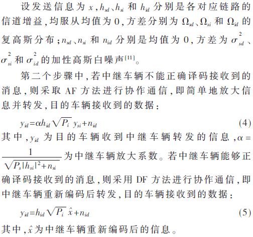
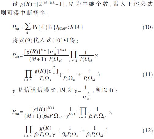
2.2 Analysis of Outage Probability
If potential relay vehicles are using HDAF scheme for collaborative forwarding. Assuming there are N relay vehicles, the link capacity of the source vehicle to the destination vehicle can be expressed as mutual information [12]:
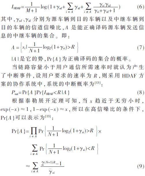
2.3 Power Optimization
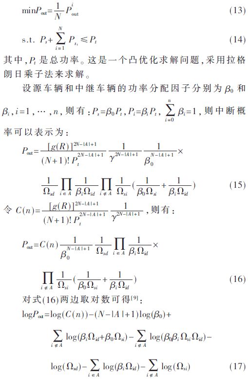
With a certain total power, try to find the best power distribution factor for the source vehicle and the relay vehicle so that the total outage probability of the system is minimized. The constraint model is as follows [9]:
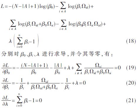
After the communication environment is determined, several results of the above formula are constants, which have no effect on the optimization result and can be ignored. Therefore, the Lagrangian cost function can be defined as:
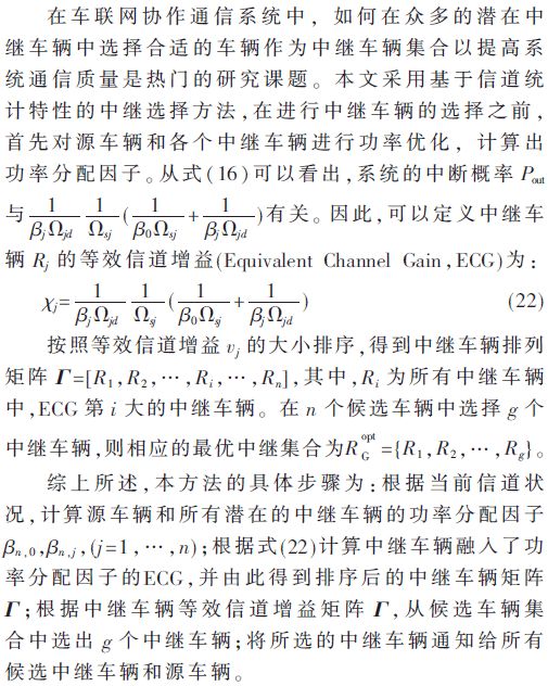
2.4 Relay Selection Algorithm
3
Numerical simulation and analysis
This section simulates the vehicle clustering method mentioned above and the relay selection method during data distribution within the cluster. The following results are the results of averaging after 1 000 random operations. The scenarios considered in the simulation are as follows: the number of road vehicles is 100, the vehicle speed is 0-30 m/s, the vehicle communication range is 150 m, and the simulation time is 50 s.
Figure 2 shows the percentage of vehicles remaining in the cluster over time. As can be seen from the figure, the clustering method proposed in this paper is slower than the vehicle-based residual ratio based on geographical clustering method, and it is higher than the latter after 15 s, and remains at around 50% with more stable clusters. structure.
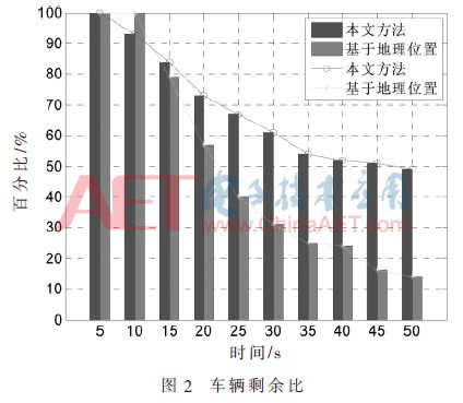
Figure 3 compares the outage probability when the number of different relay vehicles is adopted by this method. Since equation (12) is derived under high SNR conditions, the outage probability will be greater than 1 in the case of low SNR. It can be seen from the figure that when the signal-to-noise ratio is lower than 16 dB, the two relay vehicles can make the interruption probability of the system minimize when they participate in the cooperation; when the signal-to-noise ratio is greater than 16 dB and less than 23.2 dB, the three relay vehicles can participate in the cooperation. The probability of system outage is the minimum. When the signal to noise ratio is greater than 23.2 dB, four relay vehicles participate in the cooperation to minimize the outage probability of the system.
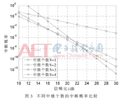
Fig. 4 and Fig. 5 analyze the outage probability of the power pre-assigned relay vehicle selection method and other relay methods using the HDAF protocol when intra-cluster vehicle data distribution in a clustered car network system. Here, the number of relays is set to 3 and the information rate R is 0.5 bit/s. Figure 4 compares the outage probability performance of AF pre-allocation relay selection using the AF protocol [9] and HDAF; Figure 5 analyzes the SAF relay. Comparison of the selection method, AAF relay selection method [14] and the outage probability of this method.
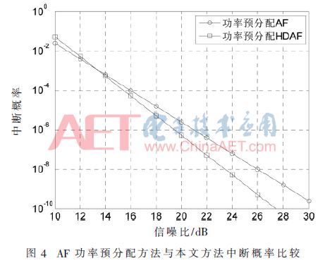
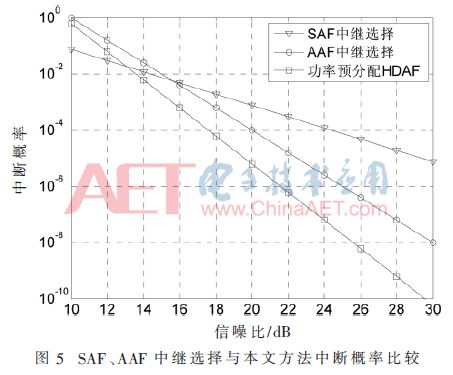
As can be seen from FIG. 4, the power pre-distribution method using the HDAF protocol has the same interruption rate as the power pre-distribution method using the AF protocol when the SNR is equal to 13 dB, and the HDAF protocol is used as the SNR increases. The probability of outage of the method is always less than the latter. It can be seen from Fig. 5 that the power pre-assignment relay selection method using the HDAF protocol proposed herein always has a lower outage probability than the conventional SAF relay selection method, and the signal-to-noise ratio when the SNR is higher than 13 dB. It is also smaller than the AAF scheme, and the proposed scheme has the best interrupt performance under the condition of high signal to noise ratio derived in the previous section.
4
in conclusion
This dissertation aims at the problem that vehicle network communication is unstable due to the rapid change of network topology in the vehicle networking system. This paper proposes a vehicle clustering algorithm based on cluster stability, makes full use of the advantages of urban public transport, and effectively increases the stability of the cluster structure. For the cooperative data distribution of vehicles in the cluster, a pre-distribution relay vehicle selection method using HDAF protocol was proposed. The simulation results show that the clustering method based on cluster stability has a more stable cluster structure than the clustering method based on geographic location; the proposed relay selection method always has a lower outage probability than the AF protocol when the signal to noise ratio is high. Allocation method, and SAF, AAF algorithm.
7.62MM Power+ Signal Power Connector
power connector is used in power module system. It can select the matching power + signal connector according to the need. The feature is that the number of power and signal contacts and the matching sequence can be selected arbitrarily while keeping the connector size and contact core number unchanged.
Plug (male) / socket (female) can be installed at 90 or 180 degrees. It supports mixed or independent combination of signal and power. The quantity range of power and signal is (2-16) pin and (12-128) pin respectively
Product features
High temperature resistant, glass fiber reinforced and flame retardant polyester is used as insulation material
Copper gold composite conductor with high conductivity is used, and the contact area of the conductor is plated with gold
It adopts shrapnel contact, which has the characteristics of integration, small volume, large current carrying capacity, soft plug-in, blind plug-in, self guidance and high dynamic contact reliability. This series of products can be interchanged with FCI's powerblade series and Tyco's multi-beam series
There are three sizes of center distance of power contact: 5.08mm, 6.35mm and 7.62mm
The length of power hole / signal pin can be selected in two sizes. The power rated current is 45A and the signal rated current is 2.5A
7.62MM Power+ Signal Power Connector
ShenZhen Antenk Electronics Co,Ltd , https://www.antenkwire.com