Usually if your design passes simulation at a lower clock frequency but fails at a higher clock frequency, your first question should be whether your design has reached timing constraints at a higher clock frequency. Requirements.
However, here we will give an example where you have checked the static timing analysis (STA) for a higher clock frequency and the timing constraints are correct.
What caused this situation to cause a higher clock frequency simulation failure?
The possible reason is that there is a problem with the simulation method, the design itself, or the testbench setting method.
However, the fact that the simulation was passed at a lower clock frequency ruled out the problem of design/testbench/simulation.
Excluding the above two items, the next one may be a pulse rejection or a pulse error.
"Pulse rejection" and "pulse error" are concepts in Verilog simulation.
These concepts say that the pulse duration is less than a certain value (pulse_r) and does not pass through a circuit component.
Of course the pulse duration is greater than pulse_r, but if less than the other value pulse_e will pass, it is shown as "x" in the simulation.
This duration is expressed as a percentage of delay through a component.
For example, the delay through a component is 1 ns.
A 0.5 ns pulse is expressed as a 50% duration.
Now assume that the design uses a frequency of 200MHz.
The corresponding period is 5ns.
Then half is 2.5ns.
In the simulation, the clock changes every 2.5 ns, that is, the width of the clock pulse is 2.5 ns.
Let us assume that the internal clock network has a pulse width of 2.8 ns (that is, greater than 2.5 ns).
Analysis results, pulse-duraTIon (pulse duration) "100%.
This pulse may be "rejected", meaning that although the clock signal can reach the input of a particular network, it cannot be output from this network.
So although the STA analysis shows that 200MHz is appropriate, the simulation does not pass.
Designing other modules will not get a clock pulse.
The solution to this simulation problem is to modify the pulse rejection and reject/error limits in the simulation settings.
For example, in ModelSim we can set:
+transport_path_delays +transport_int_delays +pulse_r/0 +pulse_e/0
Follow-up actions include:
1. Change the pulse-rejecTIon limit to 0. (will not reject any pulse)
2. Change the pulse-error limit to 0. (The output is not displayed as "x" when the pulse width is lower than a certain value)
At the same time, the interconnect delay mode is modified to transport, which actually modifies the pulse filtering option.
The final question is, are we making so many changes to pass the simulation test?
What is the actual situation in real silicon?
Most of the internal interconnects in the silicon set a repeater after every few picoseconds.
So a few nanoseconds of pulses will pass smoothly (appropriate delay), which is no problem.
The specific problem may be like this:
1. Increase in frequency (pulse width is smaller)
2. The device size increases (the internal delay of a path may become larger, resulting in an internal delay time greater than the transmission time reached by the pulse)
LED USB Cable advantage:
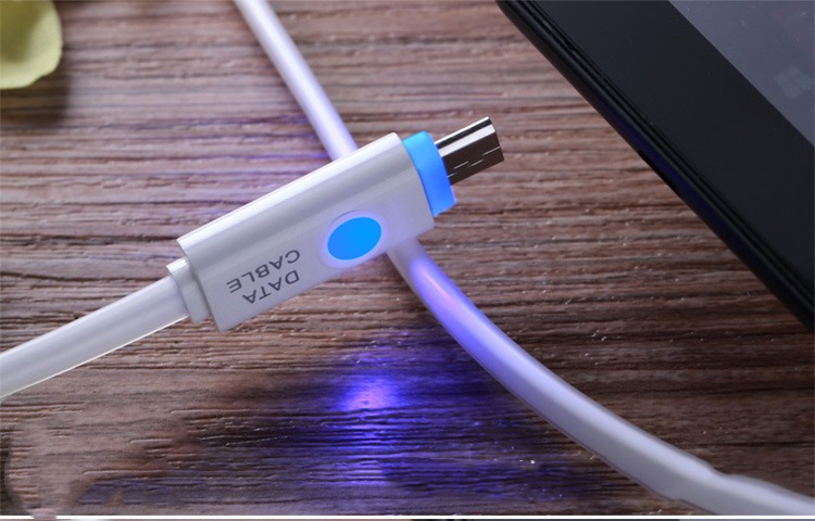
Hot selling colors gradual change color LED USB cable flashing data charging cable for ios ,for android,100% Brand New and High Quality.
Standard USB 2.0 Cable.Start syncing your phone with a PC today through this premium quality data cable.All the Cellphones with Micro USB Port

Led Usb Cable,Durable Usb Cable,Mini Usb Adapter Cable,Led Light Usb Charger Cable
Dongguan City Leya Electronic Technology Co. Ltd , https://www.dgleya.com