Environmental data monitoring system is an important part of environmental protection. Traditional environmental monitoring is the manual collection of data, and the supervision effect is poor. A wireless remote environment online monitoring system is designed for this problem. The lower computer uses Siemens S7-200 PLC (programmable controller) to collect and store field data, and actively adopts GPRS (General Packet Radio Service) DTU (Data Transmission Unit). The collected real-time data is sent to the data center, and the host computer command can be received in a specified time period to perform historical data query; the upper computer uses the Winsock control of VB 6.0 to receive data of multiple data collection terminals, and performs analysis and processing. The system has been operated in Nanhai District of Foshan City, effectively improving the efficiency of environmental supervision.
In traditional environmental monitoring, most of the staff of the Environmental Protection Agency collect data from the pollution source site and manually record the pollution control situation of the factory. Due to the large number of manufacturers to be monitored and the scattered geographical location of the manufacturers, the phenomenon of factory smuggling is very common. Even if a lot of manpower and material resources are spent, the relevant data of the pollution sources cannot be completely collected. It can be seen that the traditional artificial environment monitoring means can not meet the needs of environmental monitoring. To solve these problems, a remote environment online monitoring system is designed. The system requirements are as follows: 1 Real-time monitoring of the operating status of production equipment and pollution control equipment; 2 capable of storing within one week Data, query and complement historical data; 3 display the status of equipment in real time in an animated form, compare and analyze in the form of curves, provide objective scientific basis for pollution source supervision, and improve the modernization level of environmental protection law enforcement.
The collection of field data, remote transmission, and reliable reception of data by the host computer are the key to a successful remote monitoring system. The system uses Siemens PLC (programmable logic controllerr, programmable controller) to collect the switching information of production equipment and pollution control equipment; using industrial grade GPRS (general packet radio service) DTU (data terminal unit, data transmission Unit) transmits data; receives data using two socket (Socket) technologies that communicate with each other based on a TCP/IP (transmission control protocol/internet protocol) protocol. The data center server stores the received data in a database and displays it in the form of animations, curves, and the like.
1 system architecture
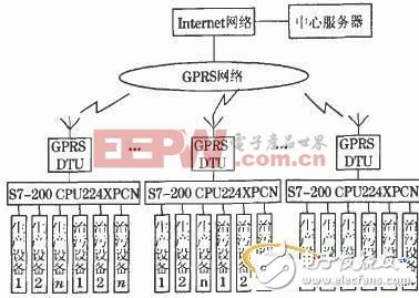
The overall structure of the system is shown in Figure 1. The system is mainly composed of three parts: Siemens S7-200CPU 224XP CN acquisition real-time data part, GPRS DTU data transmission part, EPA data center part.

Figure 1 system overall structure
1.1 PLC real-time data acquisition
The PLC reads the value of the input register IW0 in real time, packs the clock information and the device status information data, sends the data to the GPRS DTU communication module every 30S through the serial port RS 485, and then transmits it to the central server for real-time animation. And the curve and other display use, the PLC stores a record to the historical data table every 5 minutes, the historical data table can accept the data sent by the data center server in the specified time period, etc., and complete the corresponding history. Data query function and data supplement function of one day.
1.2 GPRS wireless data transmission
GPRS is a new packet data bearer service developed by superimposing a new logical entity formed by the network on the basis of the existing GSM (global system for mobilecommunicaTIon) network. The theoretical bandwidth of GPRS can reach 171.2 kbit.S-1, and the actual use bandwidth is about 10~70kbit.S-1. The bottom layer supports TCP/IP protocol, which enables GPRS to seamlessly connect with the Internet. GPRS wireless network has access speed. Fast, always online, wide coverage, low operating costs, flexible networking, and convenient system expansion.
GPRS DTU is the data terminal of GPRS network. GPRSDTU provides RS232/RS485 interface, which can be connected with serial devices such as PLC for data interaction. The baud rate, data bit and check digit of serial device are configured on GPRS DTU module. After the IP address, port and other information of the data center, the data sent by the PLC to the serial port can be transparently transmitted to the Internet network through the GPRS network, and then the data is transmitted to the data center server through the local area network.
1.3 data center server
The data center server receives and saves the data into a SQL (structured query language) database, and then performs corresponding operations on the data, and finally displays the data in the form of animations, curves, etc., providing data support for scientific law enforcement, and data. Receiving Winsock control using VB 6.0 is one of the keys of this system. In the data transmission process, the IP address of the data center server is required to be the same as the IP address in the GPRS DTU. When the system is running, the Socket monitor is started, and after establishing a communication connection with the remote data collection terminal, normal data reception can be performed.
2 PLC programming
2.1 PLC communication method
Choosing the right communication method is the key to achieving efficient data transmission. There are four communication methods for Siemens S7-200 series CPU224XP_CN.
2.1.1 point to point interface (PPI) mode
Used to communicate with Siemens programming software or Siemens' human interface products, it is a master-slave response communication mode. This type of communication requires a dedicated PPI cable.
2.1.2 multi-point interface protocol (MPTI) mode
Used to establish a small communication network between Siemens products, allowing multi-master communication and master-slave communication.
2.1.3 DP (decentralized peripheral) mode
Used to achieve high-speed communication with distributed I/O (remote I/O). Different manufacturers' PROFIBUS (process field bus) devices can be used, but special interface cards are required.
2.1.4 Free port communication mode
This type of communication allows users to define communication protocols based on their actual situation and communicate between multiple smart devices.
The PLC uploads the data to the GPRS DTU through the serial port, and then the GPRS DTU sends the data to the data center server through the wireless network. The free port communication protocol can flexibly control the communication mode of the PLC serial port through the program. Through the program control, the PLC is used as the host for most of the time, and the real-time data is actively uploaded. In the specified time period, the PLC can be the slave and accept the upper position. The machine's query command performs historical data query, which can minimize system data traffic and reduce operating costs.
2.2 PLC program
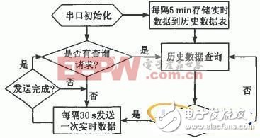
The flow of the PLC program is shown in Figure 2, using modular programming. The main program is serial port initialization subroutine, real-time data transmission subroutine, historical data storage subroutine, and historical data query interrupt program.
2.2.1 Serial Port Initialization Subroutines
S7-200 series CPU224XP_CN provides two standard RS485 ports Port0 and Port1, and Port0 is used for free port communication. Serial port initialization is mainly to set the value of some flag registers, let them communicate according to the specified way. For example, by changing the value of the special flag bit register SMB30, the baud rate, parity bit, stop bit and other information of the communication can be changed. These settings must match the values ​​of the relevant parameters of the GPRS DTU. The serial port initialization subroutine is only run once each time the PLC is restarted.

Figure 2 PLC program flow chart
2.2.2 Real-time data transmission subroutine
The S7-200 series PLC has a dedicated send command XMT in the format XMT_TABLE_PORT. The receiving command is RCV, and its format is RCV_TABLE_PORT, where PORT is the communication port, the system is set to port 0, and TABLE is the data buffer for transmitting (receiving) data. The first byte is the number of transmitted characters, the maximum is 255 bytes.
In this system, the monitored devices are relatively large devices, and do not start and stop frequently, that is, the state of the monitored object does not change frequently, and the real-time data is sent to the data center every 30 s, which can be satisfied. The real-time requirements of the system.
2.2.3 Historical data storage subroutine
The system collects the switching information (2 bytes) of the production equipment and pollution control equipment, and stores them once in the historical data table every 5 minutes. Considering that historical data is to be complemented, every 8 h (192 bytes) of data is used as a data storage unit, plus data headers and data tails, and a data area of ​​200 bytes. The historical data is saved for 7 days and needs 4 200 bytes. The historical data within the last 7 days can be stored in the PLC memory. The PLC program uses the clock information to determine the specific storage location for each data.
2.2.4 Historical Data Query Subroutines
The PLC uses the clock signal to control free port communication, allowing the PLC to allow the data center server to perform historical data query on the lower computer within a specified time period. When the data is complemented, the data (200 bytes) of the data area where the missing data is located is sent to the data center server to ensure the integrity of the database historical data.
After the query is finished, it will automatically return to the PLC to send the real-time data mode.
3 PC programming
3.1 Winsock control principle
Reliable reception of data is the key to the entire system. Socket streaming sockets are a connection-oriented socket for TCP. Direct use of Socket technology to achieve data center server and remote data terminal communication is more complicated. Therefore, the Winsock control with integrated Socket technology is adopted.
The Winsock control is a network programming interface provided by Microsoft Windows, which provides an interface implementation method based on TCP/IP protocol. It encapsulates the Windows Sockets API (applicaTIon programming interface) function associated with network communication as a whole. Use the functions to be used for network programming as the properties and methods of the control. Stable network communication functions can be achieved by calling the settings of the control-related properties and methods. This control provides users with an extremely convenient way to access TCP and UDP (user datagramprotocol) networks, and is suitable for a variety of visual programming environments such as Microsoft Access, Visual Basic, Visual C++ and Visual FoxPro.
The system has multiple data terminals, and a thread is set up for each data terminal, which is responsible for receiving and transmitting data in real time and efficiently. The Visual Basic 6.0 Winsock control array can easily implement this function, so Visual Basic 6.0 is used to develop the host computer program.
Figure 3 shows the process of data interaction between a single data terminal and a server data center. When there are multiple data terminals, the data terminal establishes a connection with the server for data interaction. The only process is to add a new Winsock control instance. Here, the control array is used. The specific method is: Add a Winsock control to the form, name it Listener, and set its Index property to 0. As the first element of the Winsock control array. Then declare a module-level variable Count in the form's Load event, set Count to 0, set the Local port property of the first control in the array to 1011 (consistent with GPRS DTU), and then call the control's Listen method. Then when the connection request is made, the code will detect if Index is 0. If it is 0, the listener will increment the value of Count and use that number to create a new control instance, then accept the new connection request with the new control instance. This completes the design of multiple terminal and server data center communication programs.

Figure 3 Single data terminal and server communication workflow
3.2 Data Center Server Receives Data
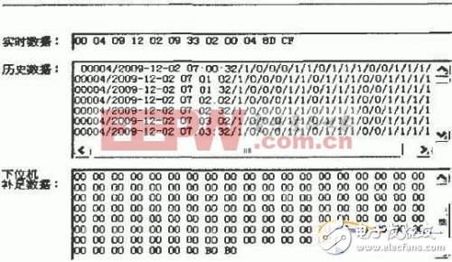
The interface of the data center server receiving PLC real-time data is shown in Figure 4. It can be seen that the received real-time data has 12 bytes and is displayed in hexadecimal. In the real-time data frame, 00 04 indicates the machine code, 09 12 02 09 33 02 00 04, indicating 09:33:02 on December 2, 2009, 00 system reserved, 04 indicates Wednesday, 8D CF indicates the switch of the device information. In the history data box, you can see the real-time data of the PLC received every 30 s, 1 means the device is on, 0 means the device is off. In the lower computer complement data frame, when the data center server detects that there is a missing data in a certain period of time in the database, the data is complemented and the obtained historical data is obtained.

Figure 4 data screen received by the host computer

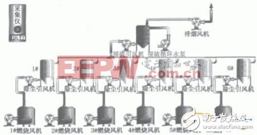
Figure 5 real-time state diagram
The server stores the received data in the SQL database, and then displays the data in the form of animation, curve, etc. in the human-machine interface of the server, vividly displaying the switch status of the pollution source production equipment and the pollution control facility, and is a scientific supervision manufacturer. The pollution control situation provides data support.
4 Conclusion
In this paper, the S7-200 PLC free port communication, GPRSDTU transparent data transmission, VB6.0 Winsock control, successfully designed the remote environment online monitoring system.
The system has been successfully operated in the Nanhai District Environmental Protection Bureau of Foshan City. The data acquisition terminal can operate stably and reliably in the harsh environment of the factory; the data center platform can observe the operation status of the production equipment and the treatment equipment in the factory in real time in the form of animation. Figure 5 shows the operation of a plant in a factory. The green light indicates that the device is running, otherwise it is red. In addition, the historical operation of production equipment and treatment equipment can be compared in a curved form to analyze whether the treatment equipment is running synchronously with the production equipment.
The remote environmental monitoring system has the characteristics of always online, reliable operation in a harsh industrial environment, and friendly interface. It can be applied not only in environmental monitoring, but also in other fields that require remote monitoring.
ZGAR AZ Mesh Vape Pods 1.0
ZGAR electronic cigarette uses high-tech R&D, food grade disposable pods and high-quality raw material. A new design of gradient our disposable vape is impressive.We equip with breathing lights in the vape pen and pods.
Our team has very high requirements for product quality, taste allocation and packaging design. Designers only use Hong Kong designers, e-cigarette liquid only imports from the United States, materials are food grade, and assembly factory wants medical grade without ground workshop.
We offer best price, high quality Mesh Pods,Pod System Vape,Pods Systems Touch Screen,Empty Pod System, Pod Vape System,Disposable Pod device,Vape Pods to all over the world.


Pod Systems Vape And Smoke,Vape Pod System Device,Pod System Vape Kit,Pod System Mini Vape Pod
ZGAR INTERNATIONAL(HK)CO., LIMITED , https://www.zgarette.com