1 Content overview
First of all, here is a general introduction to the S7-200 communication performance, please see the CPU200 and expansion module diagram (above), CPU200 will integrate 1~2 RS485 communication ports, integrated communication port can realize PPI, MPI and free port communication In terms of free port, Siemens has developed Modbus RTU master and slave communication command library-USS communication command library for customers. The first expansion module behind the CPU 200 is the CP243-2, which is the ASI master communication module. It uses two slot resources and the supported protocol version is version 2.1. The second expansion module is the EM277, which is the standard PROFIBUS DP slave communication module. The EM241 module behind the EM277 is an analog telephone modem module. The last two modules, CP243-1 and CP243-1IT, are Ethernet communication expansion modules that support the S7 protocol within Siemens. There is now a new generation of CP243-1 modules to replace the previous two modules. The IT functions of the CP243-1 mainly include Email, HTML and FTP. 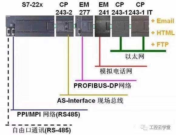
2 PPI communication
(1) PPI communication
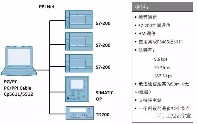
The PPI protocol was originally a point-to-point communication. It is a master-slave protocol. The master device sends a communication request to the slave device, and then the slave device responds. As the product evolves, the multi-master network is also supported. The PPI protocol is based on the communication structure of the Open Interconnect OSI 7-layer model and implements the network through Token Ring. The PPI uses 1 start bit, 1 stop bit, 8 data bits and even parity. The PPI protocol uses the RS485 communication port integrated by the CPU200 to enable programming communication, communication between the S7-200PLC, and communication with the human-machine interface. The integrated communication port of CPU200 has one PG connection resource and three OP connection resources. The supported baud rate is 9.6k, 19.2k and 187.5k, supporting multi-master stations. The farthest communication distance is 50 meters, within one network segment. Up to 32 nodes, you can use repeaters for network segment isolation and communication distance expansion
(2) PPI communication between CPUs 200
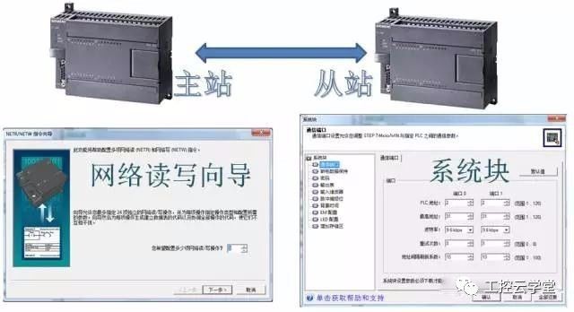
We first introduce the PPI communication between the two CPUs 200. The two S7-200PLCs here are the PPI master station and the slave station. On the master station side, the user needs to configure the network read/write wizard and use the subroutine generated by the wizard. On the slave side, you only need to set the same communication rate and different communication address in the system block as the master station.
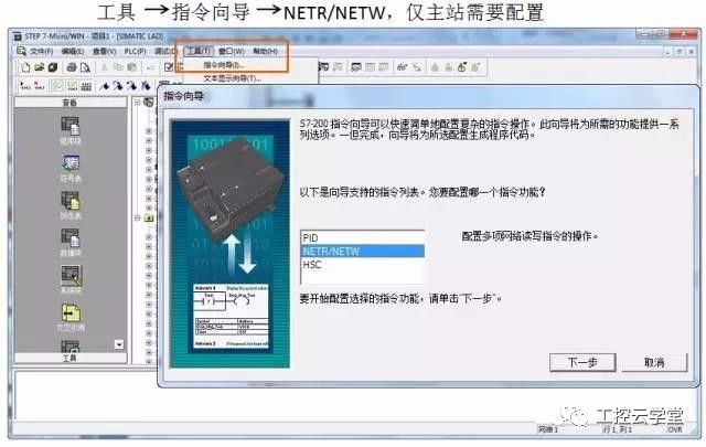
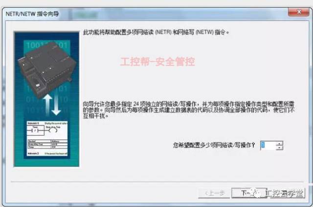
We open the S7-200 programming software, click the "Tools" drop-down menu, select the command wizard, select the network read and write wizard in the command wizard, and then click the next step (Figure 1);
This interface (Figure 2) is the first step in the wizard. The user first needs to set a total of how many network read/write operations to configure. The CPU 200 allows the user to configure up to 24 network read and write operations.
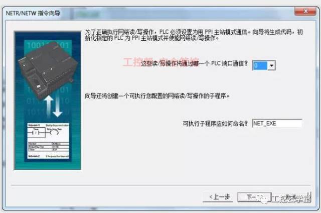
Next (Figure 3), the user chooses which communication port to use for PPI communication, 0 or 1 port. Once selected, all the network read and write operations of the wizard will pass through the port. The wizard will define a default for the subroutine. Name, the default is "NET_EXE", of course, you can also modify this name;
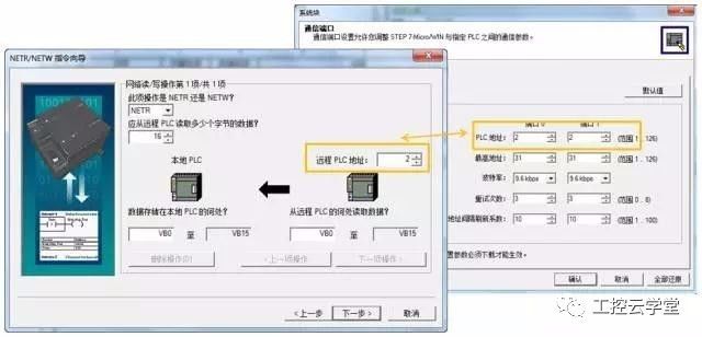
Here (Figure 4) we define each network communication read and write content one by one. First define whether this operation is network read or network write, from what address range of the remote PLC to read or write how many bytes to the local address, the effective data storage area is VB, IB, QB, MB, read and write on each network It can transfer 16 bytes of data. The address of the remote PLC must be the same as the port address in the slave PLC system block. In the example of this screenshot (Figure 4), the master station reads the VB0 from the slave to the local VB0, and reads a total of 16 bytes of data. After the configuration is complete, we can click the "Next Action" button to edit. The next network read or write operation, after all the operation configuration is completed, click the "Next" button to continue;
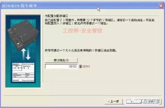
When the wizard is about to be configured, the user will be prompted to allocate an unused V memory address range (Figure 5). Each network operation requires 12 bytes of V memory address space. If two networks are configured. The read and write operations will occupy 24 bytes of V memory area address space, and the user can also define or use the suggested address to select the address range of the V memory area. It should be noted that it is necessary to ensure that the V memory area address occupied by the user program and the V memory area occupied by the network operation and the V memory area occupied by the wizard cannot be duplicated, otherwise it will result in The program does not work properly;
The Network Read and Write Wizard automatically generates a subroutine and a global symbol table (Figure 6);
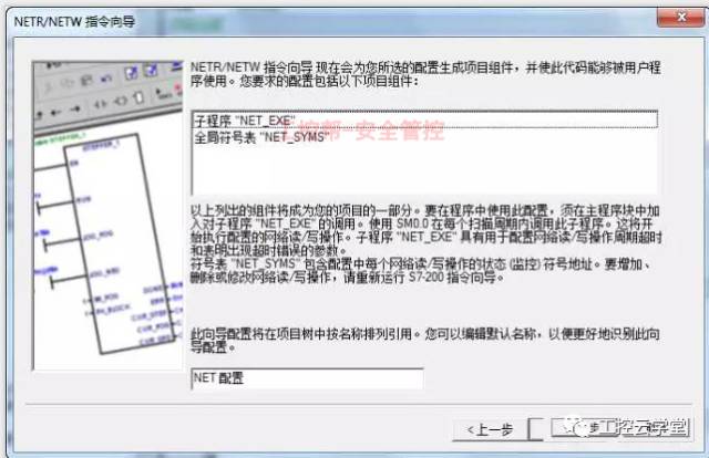
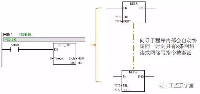
The "NET_EXE" generated by the wizard needs to be continuously called with SM0.0 in the main program. The "Timeout" input pin of the subroutine is the timeout parameter pin. If there is a problem in the communication, the waiting time exceeds this delay time, "NET_EXE" "The subroutine will report an error. Filling in 0 here (in the figure below) means that the delay detection is not started. We can specify the delay detection time in seconds. The valid data range is 1-36767.

The wizard subprogram automatically coordinates at the same time and only 8 network read or network write commands are activated.
3 MPI communication
(1) MPI communication
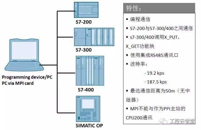
The integrated 485 interface of S7-200PLC can be used as the slave station of MPI. The programming communication of S7-200PLC can be realized through MPI communication, the communication between S7-200 and S7-300/400 integrated MPI port, and HMI man-machine equipment. Communication. For MPI communication, the baud rate supported by the S7-200PLC is 19.2kps and 187.5kps. In addition, the MPI communication device cannot exchange data with the S7-200PLC as the PPI master. .
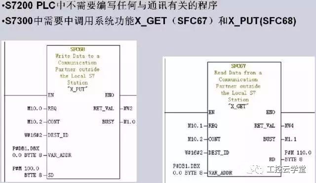
When MPI communication is used between the S7-200 and the S7-300, the S7-200 PLC does not need to write any communication-related programs. It only needs to organize the data to be exchanged into a continuous V storage area. In the S7-300PLC, the system functions "X_GET" (SFC67) and "X_PUT" (SFC68) need to be called in the program. Each read or write operation is triggered by a 1 signal input from the function pin "REQ" of the SFC, "DEST_ID" "This refers to the MPI address of the S7-200PLC, which is 2 in this example (above). The V memory area of ​​the S7-200 is regarded as DB1 by the S7-300PLC. Therefore, the "P#DB1.DBX0.0 BYTE 8" that we filled in the remote data address input pin "VAR_ADDR" starts from the S7-200PLC VB0. 8 bytes, "SD" and "RD" point to the internal data storage area of ​​the S7-300. In this example, M storage areas are used.
The Cutting Machine is a product developed for Cutting TPU Protective Films, Hydrogel Screen Protective Films and PVC Back Stickers.
Advantages of Cutting Machine:
1. "0" inventory, no need to worry about large inventory.
2. Compatible with "99%" 20000+ mobile phones, watches, tablets, etc.
3. According to needs-customize the Protective Film that customers want at any time.
4. Will not lose sales opportunities due to shortages.
5. Save product packaging and transportation costs.
6. Say goodbye to the losses caused by unsold old inventory.
7. No need to spend time and energy to find various types of products.
8. Selling new products for the first time.
9. Different styles of Protective Film can be customized.
10. Simple operation, align and paste it on the device, just one step.
11. Green environmental protection, reduce packaging, reduce waste and reduce costs.
12. To meet the needs of more customers.
13. Add value and increase sales for mobile phone stores, offline stores, and value-added services.
14. Exclusive policy, regional guarantee, first come first served.
15. Lead opponents, lead the market, and seize opportunities.
16. Regain retail market share and create higher value space.
17. New generation mobile internet Mobile Phone Protective Film customization system.
18. Quickly start the business model and start the retail business easily.
Hydrogel Cutting Machine, Mobile Phone Screen Protector Cutting Machine, Hydrogel Film Cutting Machine, Hydrogel Protective Film Cutting Machine, Hydrogel Machine
Shenzhen Jianjiantong Technology Co., Ltd. , https://www.jjtphonesticker.com