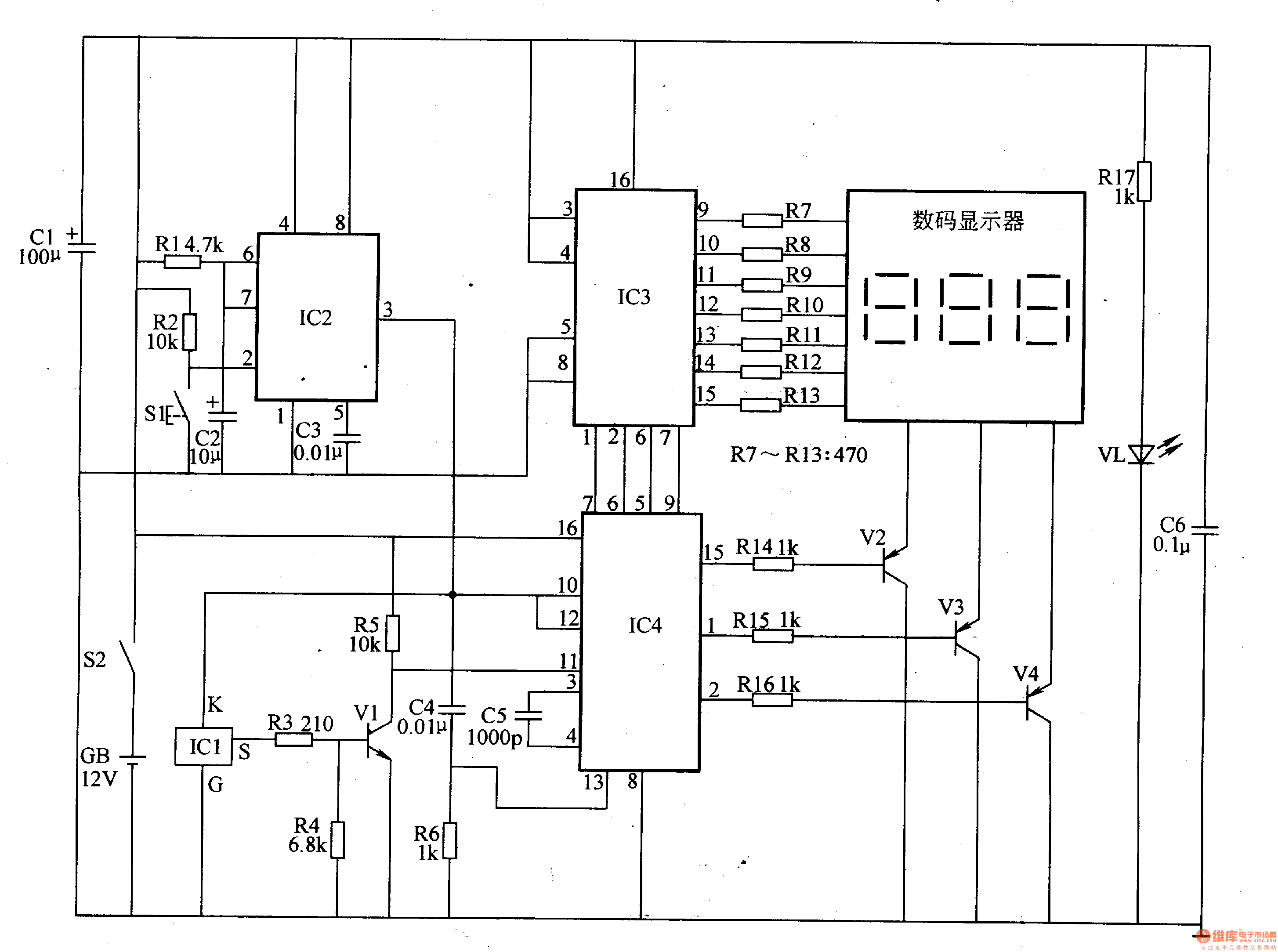
Circuit Operation Principle The electronic thermometer circuit consists of a temperature detection circuit, a monostable circuit, a digital display drive circuit, and a power supply circuit, as shown in Figure 9-133.

The temperature detecting circuit is composed of a temperature sensor integrated circuit IC1, a resistor R3-R5 and a transistor V1.
The monostable circuit is composed of resistors R1, R2, capacitors C2, C3, and time base integrated circuit IC2.
The digital display driving circuit is composed of a digital display, a counter integrated circuit IC3, a decoding driving integrated circuit IC4, a resistor R7-R16 and a transistor V2-V4.
The power circuit is composed of a power switch S2, a battery GB, a filter capacitor Cl, C6, a current limiting resistor R17, and a power indicating LED VL.
Turn on the power switch S2, GB l2V DC voltage after Cl, C6 filter, one way to IC2-IC4, the other way through R17 current limit buck, VL light.
When using, attach IC1 to the forehead of the test subject. After turning on 52, press S1, and IC3's 3 pin outputs high level (positive pulse with a width of 5Oms), so that IC4 is reset to zero and ICl is energized. . lCl converts the detected temperature information into a serial pulse signal with a frequency of 1SkHz (0-50°C corresponds to output 0-500 pulses). The signal is displayed by digital display after V1 amplification, IC4 counting and IC3 decoding. Temperature value.
After pressing the 3 pin of S1 and 1C2 to output a high level, C2 is quickly discharged through the circuit in the 7-pin of IC2, and then charged through Rl. When the voltage across C2 exceeds 8V, the circuit in IC2 flips and the 3 pin becomes Low level, ICl stops working, IC4 stops counting, and the number displayed on the digital display is the body temperature value of the measured person.
Component selection
Rl-R17 uses 1/4W metal film resistor or carbon film resistor (R7-R13 can also use integrated resistor).
Both Cl and C2 use aluminum electrolytic capacitors with a withstand voltage of 16V; C3, C4 and C6 all use monolithic capacitors; C5 uses high frequency ceramic capacitors or glass glaze capacitors.
Vl selects S9013 or 3DK4 type silicon NPN transistor for use; V2-V4 selects S8550 or 3CG8550 type silicon PNP transistor for use.
VL selects high brightness LED of φ3mm.
ICl selects AD590 type temperature sensor integrated circuit; IC2 selects NE555 type time base integrated circuit; IC3 selects CD451l or MCl4511 type decoding drive integrated circuit; IC4 selects CD4553 or MCl4553 type 3 bit BCD counter integrated circuit.
The digital display uses the BS2O1 3-digit LED digital display.
S1 selects the small moving button; S2 selects the small toggle switch or the button self-locking switch.
GB uses a l2V laminated battery.
Transparent Led Screen,Transparent Led,Led Transparent,Led Transparent Screen
Shenzhen Apexls Optoelectronic Co., Ltd , https://www.apexls-display.com