SFP is an abbreviation of SMALL FORM PLUGGABLE, which can be easily understood as an upgraded version of GBIC. The SFP module is half the size of the GBIC module, only the size of the thumb. You can configure more than double the number of ports on the same panel. The other functions of the SFP module are basically the same as the GBIC. Some switch manufacturers claim that SFP modules are miniaturized GBIC (MINI-GBIC)
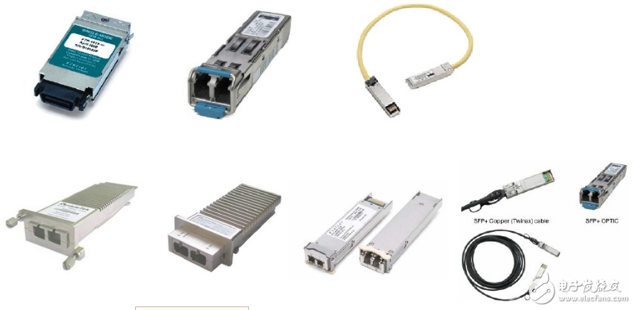
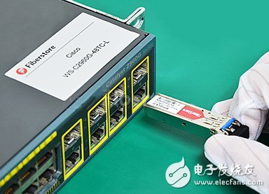
1, anti-static measures
The anti-static measures must be taken when using the optical module, whether indoors or outdoors. You must ensure that the optical module is touched by hand when wearing anti-static gloves or an anti-static wrist strap.
2, pick and place operations
It is strictly forbidden to touch the gold finger of the optical module when taking the optical module, and it must be handled gently to prevent the optical module from being pressed and bumped. If it is accidentally bumped during picking and dropping, it is not recommended to use the optical module.
3, plugging and unplugging method
When installing the optical module, first insert it into the ground with a force, then feel a slight vibration or hear the sound of “啪â€, which means that the optical module card is stuck in place. When inserting the optical module, close the handle ring; after inserting, pull out the optical module to check whether it is installed in place. If it is not pulled out, it means it has been inserted into the bottom.
When removing an optical module, you need to pull out the fiber jumper first, then pull it to 90 degrees to the optical port, and then slowly remove the optical module. Do not pull the optical module to pull out the optical module.

In order to avoid cross-contamination of the optical port due to contamination of the end face of the optical jumper, the end face of the optical fiber jumper must be clean before being inserted into the optical port. Therefore, the fiber-optic paper must be equipped with a rubbing paper to clean the end face of the fiber jumper.
If the optical module is not in use, it must be covered with a dust cap to avoid dust pollution (no fiber can be used instead of a dust cap). If the optical module is not used for a long time without a dust cap, you must use a cotton swab to clean the optical port when you use it again.
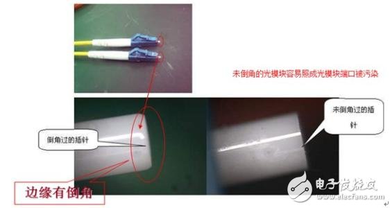
ESD is an inevitable phenomenon in nature, preventing ESD from preventing charge accumulation and allowing charge to discharge quickly.
When using the OTDR table to test the continuity or attenuation of the fiber path, you must first disconnect the fiber from the optical module. Otherwise, the optical power will be overloaded and the optical module will be burned.
The input optical power of the long-distance optical module is generally less than -7dBm. If the input is greater than -7dBm, the optical attenuator is required to increase the optical attenuation. The formula is as follows: Assume that the optical power at the transmitting end is XdBm and the optical attenuation is YdB, then the receiving end Optical power needs to meet XY "-7dBm.
Fourth, the optical port problem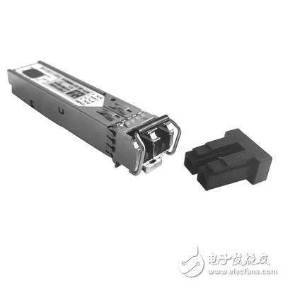
The dust-free cotton swab used in cleaning the light module needs to be selected according to the type of the optical port. Insert the dust-free cotton swab with anhydrous alcohol on the inside of the optical port and rotate it in the same direction; then dry the dust-free cotton. Insert the rod into the optical port and rotate it in the same direction;
When cleaning the end face, it is necessary to use dry and dust-free cotton. Wipe it cleanly in the non-contact part of the finger. It can't be in the same position every time. For the dirty joint, the dust-free cotton will be immersed in anhydrous alcohol (not too much). Wipe the same method as above. After wiping, replace it with another dry, dust-free cotton to ensure that the joint end is dry and then test.
Five, ESD damage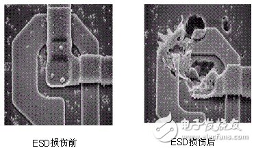
The ESD phenomenon is inevitable, but it can be prevented from both the prevention of charge accumulation and the rapid discharge of charge:
1. Keep the environment within the humidity range of 30 to 75% RH;
2. Set a specific anti-static area, use an anti-static floor or workbench;
3. The related equipment used is grounded at the common grounding point of parallel grounding to ensure the shortest grounding path, the grounding loop is the smallest, and the grounding cannot be connected in series. The design method of connecting the grounding loop with external cables should be avoided;
4. Operate in a special anti-static area. It is forbidden to place static electricity generating materials that are not necessary for work in the anti-static work area, such as plastic bags, boxes, foams, tapes, notebooks, paper sheets, personal items, etc. that are not used for anti-static treatment. Items, these materials must be more than 30cm away from static sensitive devices;
5, when packaging and turnover, use anti-static packaging and anti-static turnover box / car;
6. It is forbidden to carry out the operation of hot plugging for non-hot-swappable equipment;
7. Avoid directly detecting static-sensitive pins with a multimeter test pen;
8. Perform static protection work when operating the optical module (such as: with an electrostatic ring or discharge the static electricity by touching the chassis in advance), and contact the optical module housing to avoid touching the PIN pin of the optical module.
Supplementary explanation1. Multimode optical modules cannot be transmitted on single-mode optical fibers because the attenuation of multimode optical fibers is too large, and the transmission distance is mainly affected.
2. When transmitting a single-mode optical module with a transmission distance of more than 10km, the optical power at the receiving end cannot exceed the saturated optical power value, otherwise the receiving device may be damaged. The short optical power can be tested before connection to determine if it can be connected. If the optical power is too strong, consider using an appropriate attenuator to add additional attenuation to meet the connection requirements.
3. The 10km single-mode optical module can be transmitted on multimode fiber, and the transmission distance and the corresponding multimode optical module are the same on the multimode fiber. The main factor affecting the transmission distance is dispersion rather than attenuation.
1500W Power Station,Power Station 1500W,1500W Mini Solar System,Portable Charging Power Station
suzhou whaylan new energy technology co., ltd , https://www.whaylan.com