The design of automotive systems is becoming more and more complex as new features such as advanced driver assistance, graphical instrumentation, body control and vehicle infotainment systems are constantly being added. To ensure reliable, secure operation, each subsystem requires the use of a specific non-volatile memory to store information during reset operations and power switching. Non-volatile memory is used to store important data such as executable code or constant data, calibration data, security features, and security-related information for future retrieval purposes.
These different types of non-volatile memories are currently on the market, such as NOR flash, NAND flash, EEPROM (erasable programmable read only memory), FRAM (ferroelectric memory), MRAM (magnetic RAM) and NVSRAM (non-volatile static memory), etc. Each type of memory has its own advantages and disadvantages under different performance indicators: memory density, read and write bandwidth, interface frequency, durability, data retention, current consumption in different power modes (boot, standby/sleep, hibernation), preparation Time, sensitivity to external electromagnetic interference, etc.
In order to understand the real need of the latest automotive systems for non-volatile memory, engineers need to consider real-life use cases:
• After starting the car, is the driver willing to spend a few minutes waiting for the dashboard, odometer and fuel quantity graphics to display properly?
• The driver adjusted the seat position, steering wheel position, temperature setting, and radio channel, but for some reason had to turn off the engine immediately. If the above subsystem fails to save the settings before the car is turned off, then the driver needs to come back again, isn't it very troublesome?
• Although the car is equipped with an ADAS safety system, accidents can still occur as a vehicle. Can you provide the insurance research team with the data you need, such as the status of different sensors a few seconds before the accident?
For example, in the case of an ADAS system, it is important to collect and store real-time data from a specific sensor to a non-volatile memory. Similarly for automotive entertainment systems, it is also important to be able to store system setup information while the system is powered down. Both GIS and infotainment systems have HD graphics that not only need to store and read boot programs but also need to store and read very large configurations from external non-volatile memory.
In addition to meeting the needs of the application, non-volatile memory also needs to ensure sufficient read and write times to record at least 20 years of data. In addition, in order to achieve automotive-level certification and qualification, all subsystems should use AEC-Q100 compliant memory components. At the same time, functional safety performance in accordance with the ISO 26262 standard is another system that requires such high security requirements.
ADAS memory requirements
The ADAS system is primarily designed to automate/automatically adjust/enhance the automotive system for a safer and more comfortable driving experience. The safety function is mainly used to avoid accidents by alerting the driver to potential problems, or by implementing protective measures and taking over the control of the car to avoid collisions. Adaptive features include automatic lighting, adaptive cruise control, automatic braking, combined GPS/traffic warnings, connection to a smartphone, alerting the driver to other vehicles or dangerous conditions, keeping the driver in the right lane, and displaying the driver's Blind spot.
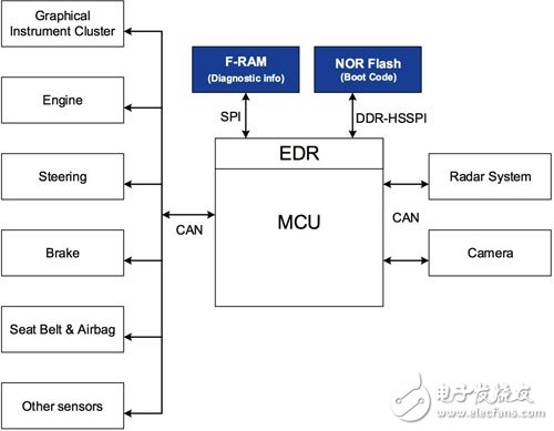
Figure 1. Block diagram of the ADAS system (Source: Cypress)
Figure 1 shows a simplified block diagram of how the ADAS system utilizes FRAM and NOR flash. External NOR flash is typically used to store boot code. However, various sensors in the ADAS system periodically send data to the MCU via the CAN (Controller Area Network) interface. The MCU runs an adaptive algorithm to check if it is possible to collide or has collided. The runtime variables of the processing algorithm and the current state of the sensor are stored in the memory of the MCU.
When the algorithm detects an accident, the airbag control module immediately activates the backup power supply and turns on the airbag to ensure that the power can be deployed during the accident. The sensor status at the time of the accident should also be immediately stored in non-volatile memory for data logging. These data can effectively help understand the cause of the accident, prompt the car manufacturer to produce a more advanced safety system, and assist the insurance company to determine whether the claim is valid.
The Driving Recorder (EDR) is a system for recording data on important subsystems prior to an accident. It can be installed in an ADAS master unit or in another MCU that receives important sensor data and communicates with the ADAS MCU. Today, engineers can use a multi-core device to provide a dedicated, complete CPU core for EDR functions, such as Cypress's TraveoTM automotive microcontrollers.
EDR judges the collision by measuring the impact force, vehicle speed, engine speed, steering input, throttle position, braking status, seat belt status (detecting passengers), tire pressure, warning signal and airbag opening status of the front pressure sensor of the car. degree. And the above data is recorded before and during the collision of the car. Obviously, the microcontroller can't wait until an accident occurs to start recording data. Therefore, the microcontroller needs to store data continuously. Therefore, EDR requires a non-volatile memory with almost unlimited write times.
FRAM memory has more advantages than ADAS's traditional EEPROM. It is critical for ADAS to store critical data (actually 10us storage time) in real time without writing waits. EEPROMs typically require write latency of more than 10 milliseconds and are therefore not suitable for high security applications. FRAM has both write-free latency and high-speed clock speed, making it ideal for applications that need to write large amounts of data quickly. When using SPI, the designer is free to determine the number of bytes written to FRAM. When writing one or two bytes to a random location in FRAM, the write cycle is approximately 1 microsecond. In contrast to EEPROM or flash, a write cycle of 5 - 10 milliseconds is required.
Unlike EEPROM or flash, FRAM does not require a page buffer. After receiving the 8th bit of each byte, FRAM writes each data byte immediately. This means that when the system memory density grows, engineers don't have to worry about page buffer size changes.
In terms of write endurance, FRAM can support 10 billion write operations, far exceeding 1 million EEPROMs and 100,000 flash memories. Therefore, FRAM can be used as a trace data logger to continuously write data. In addition, FRAM writes and reads very low power (for example, 300 microamps at 1 Mhz), making it ideal for ADAS applications that require low-power backup power or data to be written via capacitors in the event of an outage. FRAM has a much lower standby current (typically 100 microamps) compared to other nonvolatile memories.
Car dashboard requirements for memory
The dashboard system displays important information such as speed, speed, fuel level and engine temperature on a graphical display in digital form, or in an analog form controlled by a stepper motor. In addition, the dashboard system can also display battery warnings, temperature warnings, low oil pressure warnings, brake warnings, seat belt status indicators, low tire pressure signs, door lock signs, headlight signs, shift indications, handbrake status indications, and In- and outside temperature, odometer readings, etc.
The latest dashboard system also includes a head-up display (HUD). A head-up display is an optical system that projects driving information onto the windshield of a car. With a head-up display, the driver can easily view important driving information while keeping his eyes on the traffic ahead. This reduces the potential risk of leaving the road and gives the driver extra time to identify and react to risk factors. Head-up displays display speed, navigation, and other important warning symbols.
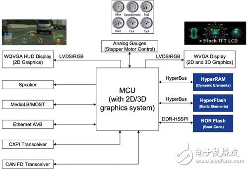
Figure 2. Dashboard system block diagram (Source: Cypress)
Figure 2 shows a simplified block diagram of the dashboard installed around HyperRAM and HyperFlash (connected to the HyperBus interface) and NOR flash (connected to the DDR-HSSPI interface). The dashboard MCU can connect to other subsystems through different communication protocols such as CAN-FD, CXPI (Clock Extended Peripheral Interface), Ethernet AVB, MediaLB (Media Local Bus)/MOST (Media Oriented System Transmission) to collect information and Displayed on the dashboard.
Once the dashboard system is started, the security engine immediately verifies the authenticity of the firmware. Subsequently, XiP is executed from the NOR flash memory through the HyperBus interface from the external HyperFlash or through the DDR-switched DDR-HSSPI interface, and the MCU software starts execution. The XiP feature allows the MCU to execute code directly from external memory without having to copy the external flash code to internal RAM first, which improves responsiveness. NOR Flash/HyperFlash Memory configures the initial address location of the program code and starts in read mode after a specified clock delay. Therefore, once the MCU is started, it can directly acquire the code that needs to be executed without delaying the time by providing the address and reading the command.
Static elements can be obtained from external HyperFlash and displayed as the base layer of the dashboard LCD. Automotive MCUs, such as the Cypress TraveoTM series, provide additional feature support to instantly decompress static HMI elements without first passing through RAM. Dynamic content such as dashboard needle information has a faster update rate and can be retrieved from external HyperRAM.
Memory requirements for HVAC and infotainment systems
The HVAC (Heating, Ventilation and Air Conditioning) system is responsible for controlling the temperature and air flow inside the vehicle. The infotainment system can run a variety of applications similar to smartphones and provides a user interface to change HVAC system configuration, music system settings, enter destinations in navigation applications, adjust seat/steering wheel position/height, and adjust interior lighting, etc. . Some of the latest cars have also added fingerprint readers to verify driver identity. This allows HVAC and infotainment systems to quickly adjust in-vehicle settings to the driver's preferences.
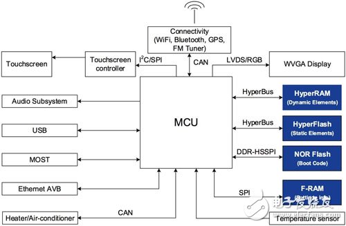
Figure 3. Block diagram of HVAC and infotainment systems (Source: Cypress)
Figure 3 shows a simplified block diagram of HVAC and infotainment systems with all memory connected to the main MCU. Three additional subsystems are compared to the dashboard system:
• Touch screen controller for detecting finger touch on the display
•Heater/air conditioner to control the temperature inside the car
• Connect subsystems to achieve multiple connections in the car (Bluetooth, GPS, WiFi, GSM, FM tuner, etc.)
HyperFlash and HyperRAM memory are used to store high quality graphics. NOR flash is used to store boot code, while FRAM is used to store setup information. Therefore, even if the car is turned off immediately after the engine is turned off, the car settings can be retrieved and restored correctly.
Memory interface
The requirements for non-volatile memory in different automotive fields have been discussed above, and the different interface mechanisms between these memories and MCUs are discussed.
All MCUs with SPI interface can easily connect to NOR flash. NOR flash devices, such as Cypress's S25FL256L, offer multiple I/O read-in options for SPI, supporting double data rate (DDR) and quad peripheral interface (QPI) connections. Multiple flash memories can be connected on the same bus and individually accessed using chip select (CS) signals.
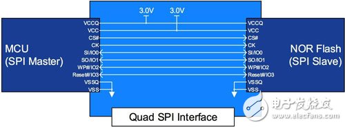
Figure 4. NOR flash interface to a four-channel SPI (Source: Cypress)
Figure 4 shows the hardware connection between the MCU and the NOR flash. The MCU can read, program, and erase the NOR flash using low-level driver (LLD) software. The optimized design architecture speeds up access times and speeds up the program. At the same time, the internal technology used by NOR flash determines the density of the memory. NOR flash uses traditional floating gate technology. On the conductive layer, each memory cell can store 1 data bit. NOR flash memory built on MirrorBit technology insulation, each memory cell can store 2 data bits, providing a lower cost 256 Mb or greater density storage structure.
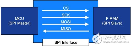
Figure 5. F RAM memory interface to the SPI (Source: Cypress)
Figure 5 shows how to access FRAM using a simple SPI interface. For microcontroller-based systems with high-speed serial data rate requirements, the SPI interface is ideal. Serial data throughput is related to the serial clock frequency. The serial FRAM has a clock frequency of up to 40 Mhz. Microcontrollers that do not have a dedicated SPI port can implement “bit bang†via GPIO (analog serial communication via software via GPIO pins).
HyperFlash and HyperRAM can be accessed through the HyperBus 12 signal interface. Compared to Quad-SPI (66.5 Mbps), HyperBus provides up to 333 Mbps of read throughput with only one-third the number of pins required for parallel NOR flash. This interface uses a differential clock (CK, CK#), a read and write data strobe (RWDS), a chip select, and an 8-bit data bus.
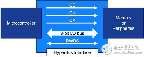
Figure 6: HyperBus interface between memory and peripherals (Source: Cypress)
Data integrity and security
Data integrity and security are two important factors in choosing automotive application memory. The memory described in this article provides a variety of features to improve data integrity and security. For example, Advanced Sector Protection (ASP) technology provides higher resolution and different power-on resets for locked sectors and helps run secure boot code. At the basic level, the principle of ASP technology is simple. Any sector can be locked to prevent programming and deletion. There are two ASP modes for locking sectors: Persistent Protection Bit (PPB) and Dynamic Protection Bit (DYB) protection. In addition to the block protection (BP) and/or WP# pin hardware protection, the above two modes can also be used together.
The Automatic Error Correction Code (ECC) feature operates transparently during standard programming, erasing, and reading operations. When the device transfers each page of data from the write buffer to the storage array, the internal ECC logic evaluates the page's ECC code as part of the storage array that is invisible to the host system. Each time the initial page is accessed, the device evaluates the page data and ECC code to verify the integrity of the page. If necessary, the internal ECC logic corrects the 1-bit error on initial access.
NOR flash also provides additional flash memory that can be programmed once and is permanently protected and cannot be changed. Taking Cypress's FL-S NOR flash family as an example, this one-time programmable (OTP) has a 1K protected area with a 512-byte factory-protected lock area and a 512-byte user protection lock area.
to sum up
Today's automotive systems require a variety of memory types that provide different levels of reliability, responsiveness and throughput to meet individualized needs in different automotive subsystems. By choosing the right combination of memory, engineers can ensure reliable and safe operation of the car while meeting the driver's expectations for responsiveness.
Ningbo Autrends International Trade Co.,Ltd. , https://www.supermosvape.com