The ultrasonic remote control dimming and speed governor introduced in this example can not only control the on and off of the household appliance power supply, but also remotely control the dimming control of the lighting, and remotely control the electric fan. Device.
Circuit Operation Principle The ultrasonic remote control dimming and governor circuit consists of two parts: an ultrasonic transmitting circuit and an ultrasonic receiving control circuit.
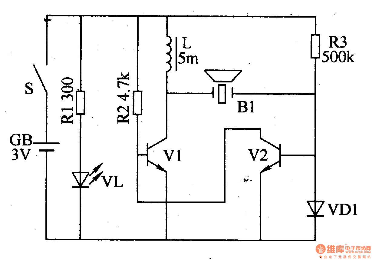
The ultrasonic transmitting circuit is composed of transistors V1, V2, control switch S, battery GB, diode VD1, resistor Rl-R3, inductor ", light-emitting diode VL and ultrasonic transmitter B1, as shown in Figure 3-160. 
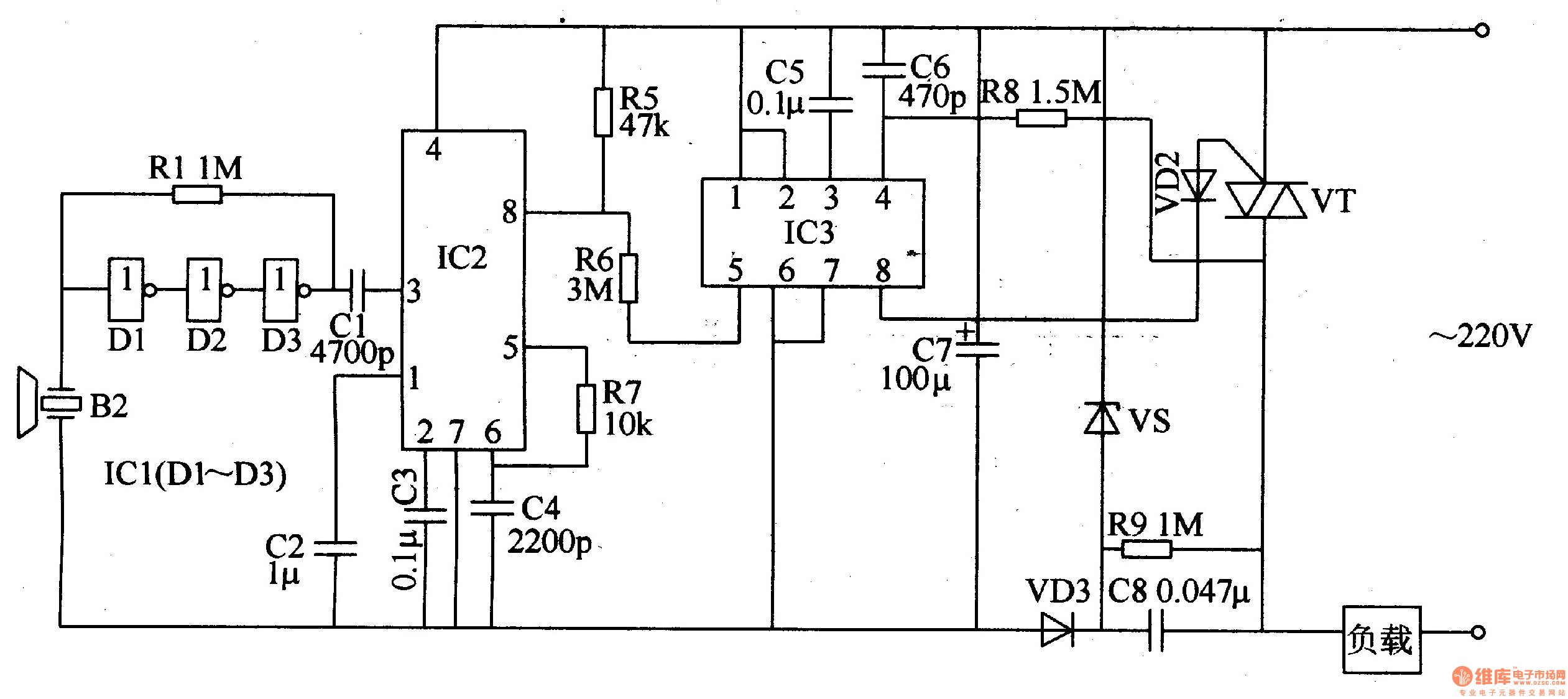
The ultrasonic receiving control circuit is composed of an ultrasonic receiver B2, an input amplifier, a demodulator, a dimming/speed control circuit, and a power supply circuit, as shown in Figure 3-161.

The power circuit is composed of a step-down capacitor C8, a resistor R9, a Zener diode VS, a rectifier diode VD3, and a filter capacitor C7.
The input amplifier is composed of a non-gate integrated circuit ICI (Dl-D3) and a resistor R4.
The demodulator consists of a phase-locked loop decoder integrated circuit IC2 and a capacitor Cl-C4, resistors R5, R7.
The dimming/speed control circuit consists of a stepless dimming integrated circuit IC3, resistors R6 and R8, capacitors C5 and C6, a diode VD2 and a thyristor VT.
The AC 220V voltage is supplied to the lCl-IC3 through the load (electrical equipment) and C8 step-down, VS voltage regulation, VD3 rectification and C7 filtering.
When S is pressed, the positive feedback oscillation circuit composed of Vl, V2 and R2, R3, L, VDl is energized to generate an oscillation signal of 4OkHz. This signal is transmitted by an ultrasonic signal converted from B1 to 4OkHz. While pressing S, VL emits light.
B2 receives the 4OkHz ultrasonic signal transmitted by Bl and converts the signal into an electrical signal, and then sends it to the input amplifier for buffer amplification. After the signal amplified by ICl is demodulated by the demodulator, a pulse signal is generated as an input control signal of the dimming/speed control circuit. Each time you press 5, the 8th pin of 1C2 outputs a negative pulse.
If S is pressed for a short time (the system is within 0.4s when pressed), IC3 outputs a trigger control signal to turn on VT and the power of the controlled appliance is turned on. If used to control the light, then the light will be illuminated. When S is pressed again for a short time, the illumination goes out.
If S is pressed for a long time (when the board is greater than 0.4s), IC3 outputs a change control signal to change the conduction angle of VT. When it is used to control the illuminator, after the illuminator is lit, the brightness of the light will gradually change from dark to dark, and then gradually change from bright to dark. When the brightness is considered to be appropriate, release S and the brightness of the light is fixed. To turn off the light, just press S for a short time.
Component selection
Rl-R8 selects 1/4W carbon membrane resistor or metal membrane resistor for use; R9 selects 1/2W metal membrane resistor for use.
Cl, C4 and C6 use high frequency ceramic capacitors; C2, C3 and C5 use monolithic capacitors or polyester capacitors; C7 selects aluminum electrolytic capacitors with a withstand voltage of 16V; C8 selects polyester capacitors or CBB with a withstand voltage of 400V Capacitor.
VDl and VD2 select lN4148 type silicon switch diode for use; VD3 selects 1N4007 type silicon rectifier diode for use.
VS selects 1W, 6.2V silicon steady voltage diode.
VL selects φ3mm high brightness LED.
Both Vl and VZ use the Model 59013 or 59014, Model 58050 silicon NPN transistor.
VT selects TLC336A type 3A, 600V bidirectional thyristor.
L selects TDK color code inductor.
ICl selects CD4069 type six non-gate integrated circuit; IC2 selects LM567 type phase-locked loop decoder integrated circuit; IC3 selects SM7232 type CMOS touch dimming integrated circuit.
B1 selects UCM-40T ultrasonic transmitter; B2 selects UCM-40R ultrasonic receiver.
Energy Saving Sewing Machine Motor
Energy Saving Sewing Machine Motor,Single Sewing Machine Motor,Industrial Servo Motor,Single Phase Motor
LISHUI SHUANGZHENG MOTOR CO.,LTD. , https://www.szservomotor.com