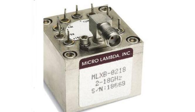
The generation of microwave frequencies requires many exotic structures, including Gunn diodes, dielectric resonators, and carefully-cut quartz crystal plates. But perhaps no resonator manufacturing method is like blowing a yttrium iron garnet (YIG) ball microwave source placed in a cavity with an electromagnetic field. After years of research on the technology, engineers at MICRO Lambda Wireless have finally developed the highest performing YIG oscillators to date: MLXB with continuous adjustment and fundamental frequency range between 2 and 18 GHz and between 2 and 20 GHz. Ultra-wideband series oscillators, which use band switching, MLXS-T series wideband oscillators with a fundamental frequency range of 2 to 18 GHz and 2 to 20 GHz.
Wideband YIG oscillators are used in many systems, such as local oscillators (LOs) in receivers and spectrum analyzers, microwave sources in frequency synthesizers, and anti-terror simulators and broadband electronic warfare. Used as a signal generator in the system.

It takes skill and time to assemble a YIG oscillator, but its excellent low noise performance is worth the effort. The YIG oscillator is formed by placing a tiny YIG ball exactly in the air gap of the electromagnet. In a well-designed YIG oscillator, the electromagnetic field strength is a linear function of the applied current, which in turn determines the tuning behavior of the final YIG oscillator. The wire loop couples energy from the electromagnet to the ball; similarly, the coupling ring extracts the resonant energy produced by the YIG ball, which in turn produces the output frequency of the YIG oscillator. The energy storage circuit that resonates with the YIG ball is designed according to the requirements of the coil of the electromagnet and the ball itself. In order to produce a high quality output signal, the circuit is designed with a high unloaded quality factor (Q).
In order to produce output level requirements that meet the aforementioned applications, the YIG oscillator contains transistors that are used to boost the signal level of the final output. For this function, bipolar transistors have been used in the past, but as the frequency of YIG oscillators has increased (above 20 GHz), people have started to use GaAs FETs. Recently, in order to take advantage of the excellent low noise performance of these devices, silicon germanium has been used. (SiGe) transistor. In some cases, monolithic microwave integrated circuit (MMIC) amplifiers have been used to replace discrete device circuits used in the past to boost output stage levels.
The primary coil in the YIG oscillator is responsible for frequency tuning, but the secondary coil is also required when generating frequency modulation (FM) or stabilizing the output frequency to an external reference source (as in a PLL oscillator or synthesizer). Like the main coil, the FM coil is tuned by current. In order to work with modern PLL integrated circuits, the FM loop should have the ability to produce wideband modulation frequency offsets and have sufficiently high tuning sensitivity.
In fact, broadband YIG oscillators were previously available on the market, but they all have no fundamental output. Several manufacturers have achieved output frequencies of up to 18 or 20 GHz by integrating lower frequency pitch YIG oscillators with frequency multipliers and wideband output amplifiers in a standard columnar YIG package. The MLXB Ultra Wideband Series YIG Oscillator (Figure 1) and the MLXST Series Band Switched YIG Oscillator (Figure 2) provide a baseband output but do not use a multiplier.
The MLXB ultra-wideband series of YIG oscillators currently has four products, two of which have a frequency range of 2-18 GHz and the other two have a frequency range of 2-20 GHz (Table 1). The lower frequency products have an output power of no less than +13 dBm over the entire frequency range, while the higher frequency products have an output power of no less than +12 dBm over the entire frequency range; over the entire bandwidth tuning range All four products have output power flatness within ±3dB. The four YIG oscillators draw up to 100mA from a +15VDC supply and 20mA from a +5VDC supply. They also use a +24VDC supply (with a variation range of ±4V, a maximum surge current of 250 mA, and a steady-state current of 25 mA) powers the internal heater circuit of the YIG source.
Kindwin Technology (H.K.) Limited , https://www.szktlled.com