Is Near Field Communication (NFC) still in a state of speculation and trade-offs? Obviously not! The technology was previously only seen as a new generation of barcodes, which proved to be much more practical and reliable. In many consumer and industrial markets, NFC and radio frequency identification (RFID) capabilities are required. These applications are no longer limited to traditional simple, intuitive, and secure contactless data exchange. Flexible exchange of information between two NFC/RFID-enabled devices (phone numbers, photos, poster data, etc.), what you need to do Just bring them together. The main concepts and traditional applications of NFC/RFID are evolving with new, non-traditional ways of thinking. In fact, we are in an era of innovation.
You may often hear the question "What is the difference between NFC and traditional RFID?" In the physical layer or RF layer, the difference is really not too big! NFC is essentially an evolutionary form of RFID. In fact, NFC works in the 13.56 MHz band (HF) of RFID. The industry alliance NFC Forum 1 began with an RFID physical layer protocol and improved by adding several new layers to the protocol stack. The NFC Data Interchange Format (NDEF) has been added to identify, encapsulate, and exchange application data between NFC-enabled devices. This standardized format makes NFC/RFID an emerging wireless communication technology with a promising future that adapts to future ubiquitous computing.
To cover a wider range of applications, RFID and NFC are used interchangeably in the discussion that follows. We will briefly introduce NFC/RFID technology and give common circuit modules that OEMs can use to implement new contactless NFC/RFID functions in portable electronics. The example circuit is based on the DeepCover MAX66242 dual interface secure passive tag. With the given circuit, it is easy to add NFC/RFID short-range wireless technology to the embedded electronic platform. We will discuss this in combination with several practical uses.
Card readers and tags: NFC/RFID basicsIt is a standard short-range wireless communication technology that supports communication between handheld or other devices that are relatively close to each other. NFC/RFID works from a few inches to 1 meter. This technique uses inductive coupling, a process that transfers energy through a common magnetic field between two devices. This process is actually the same as that of an air-core transformer. The reader antenna coil is equivalent to the primary side, and the antenna coil of the tag is equivalent to the secondary side. The card reader uses electromagnetic induction to generate a tag that can detect the resulting radio wave. Thus, as the tag approaches the card reader, the electrical waves generated by the reader antenna coil will couple to the tag antenna coil. A voltage is induced in the tag, which is then rectified and powered by the tag's internal circuitry.
Figure 1 shows how the card reader modulates the electrical waves and exchanges data with the tags. In order to transfer data from the tag to the card reader, the tag circuit changes its coil loading (while the unmodulated carrier of the card reader remains open); mutual coupling allows the card reader to detect this change. This load change method is called load modulation. NFC/RFID operates at 13.56 MHz and is a worldwide license-free ISM band. There are several standard specifications that have been issued for this technology, including ISO/IEC 14443 Types A&B and ISO/IEC 15693.
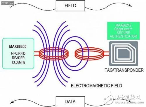
Figure 1. The magnetic field of the NFC/RFID tag (MAX66242) coupled to the card reader (MAX66300).
In this example, the MAX66242 is a passive IC that can operate passive tags without the need for an external power supply. In fact, passive tags get energy from the magnetic field of the reader. Typical applications using this NFC/RFID technology include access control, smart posters, membership cards and coupons, mobile payments (contactless credit cards), ticketing and shipping charges.
Working principle - passive tag authenticatorDesigners can now use portable electronics to collect and exchange configuration/calibration data for safety systems, even if the mains power to the portable device is lost. The solution shown in Figure 1 allows any embedded electronic product to be wirelessly connected to any device in the vicinity and through I? The C interface is connected to the network.
Several features are important for wireless NFC/RFID applications: advanced security integrated into the passive tag authenticator (Figure 2), integrated wireless NFC/RFID interface and I? C interface, data protection mode, high-speed data transmission, tag energy collection; MAX66242 integrates SHA-256 encryption engine to provide symmetric key-answer security authentication based on security key. It is the best way to control how NFC/RFID readers communicate with those devices and how to communicate with the MAX66242. Is the 32-byte SRAM buffer beneficial for I? The C interface performs high speed data transmission. The energy harvesting pin VOUT on the tag allows the antenna to collect energy from the HF field of the reader.
Thanks to the advantages of SHA-256 secure encryption, high-speed data transmission and energy harvesting, this passive tag is extremely attractive for OEMs who want to use NFC/RFID embedded portable systems for open and scalable platforms. .
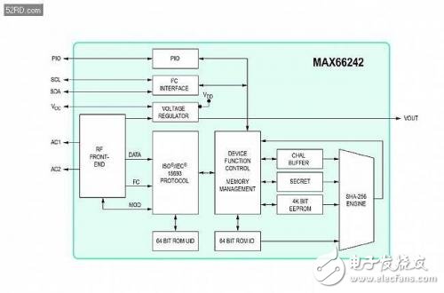
Figure 2. Functional block diagram of the MAX66342 passive tag.
Guarantee data security - only trust genuine slave devicesSecure, symmetric, and two-way security authentication between the reader and the slave using the SHA-256 encryption engine. The SHA-256 hash algorithm is based on the secure hash standard FIPS PUB 180-4 issued by the National Institute of Standards and Technology (NIST). The SHA-256 challenge-response security mechanism exchanges data between the master and slave devices, which is the best way to control which devices the NFC/RFID reader communicates with and how to communicate with the MAX66242 passive tag.
The two-way, secure authentication based on the symmetric key, the card reader (ie the initiator) only accepts the genuine label; only the genuine card reader can change the label's memory. This method assumes that the portable device (using the MAX66242) and the card reader system have the same SHA-256 security algorithm. When SHA-256 is activated, the portable device must first provide a valid response or response to the NFC/RFID reader for secure authentication. And the response of the portable device is related to the received challenge and its stored key. If the portable device answers the challenge incorrectly, the card reader system (such as a smart phone) will reject the portable device.
The main elements of this secure authentication mechanism include a 256-bit random challenge, the ROM ID of the MAX66242, and the key itself. The ROM ID is a unique 64-bit serial number that is embedded in the tag during the manufacturing process. The same key must be set and protected in the reader. Figure 3 shows an example of a security door card application where NFC/RFID initiates challenge-response authentication before opening a room door, fire door or bulletproof door.
To ensure that (inevitable) malicious attacks against such secure ICs are prevented in the most economical form, passive tags use proprietary die-level physical techniques and corresponding circuitry and encryption methods. These protection techniques prevent an attacker from extracting a key (to compromise the security of the system) in order to clone a key or change proprietary calibration data.
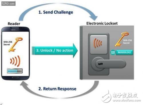
Figure 3. NFC/RFID-based electronic lock security certification is at the heart of the MAX66242 passive tag.
Ensure the security of data protection measuresProtecting data security is critical, so the MAX66242 provides a 4K-bit user EEPROM that can be divided into open access areas (such as no protection) or areas where the card reader must be securely authenticated by EEPROM write operations. Multiple protection modes are available, including EPROM emulation (EM) mode, which allows the use of non-resettable counters and limits the number of uses. When the EM mode is activated, the individual memory bits in the tag can only change from 1 to 0, but cannot change from 0 to 1. Once the EM mode is selected, it is irreversible. This process is the best way to count down or limit the number of times a portable device is used, and is probably the most challenging job.
The model also gives OEMs better control over which NFC/RFID reader system connections are available, which is a great way to protect calibration, configuration and diagnostic data stored in the device.
High-speed data transfer without external microcontrollerIs the MAX66242 passive tag I? C to NFC/RFID protocol converter gateway. Label I? The C port can be used as a host port or a slave port for data exchange. In the application shown in Figure 3, the NFC/RFID reader can access I-based? The electronic component of C, which is directly connected to the MAX66242. So you don't need an additional microcontroller (such as mounted on a sensor card) to access the data.
As mentioned above, does the IC's integrated 32-byte SRAM buffer help speed up I? C to HF data transmission. Similar to the scheme in which data must be transferred through its EEPROM unit, the MAX66242 in the example uses its SRAM buffer to manage such transfers. SRAM access times are faster than EEPROM, which is an advantage over other solutions to speed up the overall transaction processing of the system.
The IC also provides programmable input/output (PIO) pins for versatile applications, including microcontrollers that interrupt portable devices in specific applications. The PIO pin can be configured as an RF Busy or RF-Access-In-Progress alarm signal. An excellent use of the alarm signal is to wake up the sleeping embedded system in the presence of a 13.56 MHz HF electromagnetic field. In short, this versatile PIO pin provides a better way to control system data flow.
Energy harvesting for increased flexibility and scalabilityEnergy harvesting is very useful, making the MAX66242 a highly flexible and scalable solution for a wide range of NFC/RFID applications.
As a universal passive tag, the IC does not require external power supply; it can work with very low power consumption, about 50? A, or a slight change depending on the features supported. The tag collects energy from the reader's 13.56 MHz HF electromagnetic field. When the antenna is properly constructed and tuned for efficient, optimized links, the energy obtained by the passive tag is much higher than the power required by itself. The remaining energy is often shunted to the ground. In contrast, in the MAX66242, the unused collector energy is output to the IC's external circuitry through the IC's VOUT pin. That is, the collected energy can be used for power supply to the periphery of the IC, such as a temperature sensor, and temperature conversion data is also collected from the sensor. The IC's VOUT pin can be configured to provide 1.8V or 3.3V (typ) voltage, and the configurable power supply provides up to 5mA when the field is strong enough.
Optimize antenna design for maximum power and efficiencyThe passive tag energy extraction method is more effective only when the optimal RF circuit design is achieved and the RF energy is transmitted to the maximum extent. The efficiency of energy transfer between the card reader and the tag antenna coil is highly dependent on the accuracy of the resonant circuit and/or the way the antenna is tuned. The effective absorption or transfer of energy between the antenna coils is achieved by electrical resonance. At this point, it is critical that the antenna coil of the MAX66242 tag and its tuning capacitor resonate at 13.56 MHz.
The antenna design principle is relatively simple and clear. The tag antenna inductance (LINDUCTOR) must be constructed on the PCB (or inner substrate) to match the on-chip tuning capacitor (CTUNING) to achieve an IC resonance of 13.56 MHz. Therefore, the sum of all capacitor and inductor reactance must be zero. When is LCw? = LC (2Ï€f)? This condition is met when = 1 (with f = fRES). This theoretically means that the energy flow (IRF flow) flowing into the MAX66242 tag is maximized, or the impedance is minimized. Thereby, the resonance frequencies fRES and LINDUCTOR in the equation 1 are obtained.

Equation 1. The integrated external antenna inductance (LINDUCTOR) on the PCB must match the tag's internal tuning capacitor (CTUNING) to provide a circuit resonance point of 13.56 MHz.
Satisfying the above formula means that the tuning circuit resonates. Equation 1 can also be used as an example of calculating the actual LINDUCTOR when the CTUNING value is known. After calculating the L value, the designer will construct an external antenna to get the L value. After achieving the above conditions, the antenna design has maximized the current received by the LC loop.
It is worth noting that in practical applications, design engineers always maximize the power of real systems by designing NFC/RFID antenna coils. Since the tag is installed in the HF field, there is often a tag "loading effect". To account for this loading effect, the antenna coil designer may have to design it to overshoot or undershoot, ie slightly below or above 13.56 MHz, making the circuit more efficient. How to build an antenna is beyond the scope of this article.
Embed in a portable deviceObjectively speaking, NFC/RFID is opening the door to the market for wearable technology. Under the tide of the Internet of Things (IoT), more and more embedded systems supporting sensors will emerge, collecting users' biological and other data through various systems on the network; there will be a lot of medical and NFC/RFID-enabled technologies. Industrial applications have emerged, and we are still unclear about its scale.
Before we discuss a specific application, let's first look at the basic circuit structure that supports NFC/RFID in embedded designs (Figure 4). Note that the system needs to have a way to communicate with the outside world.
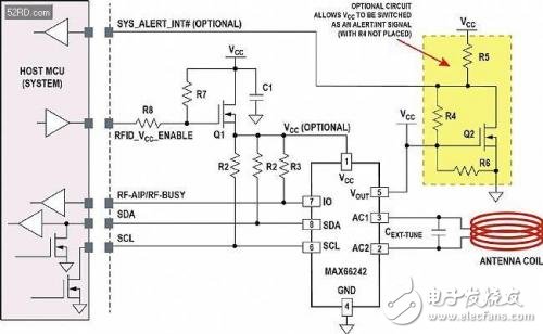
Figure 4. Typical circuit diagram for supporting NFC/RFID functionality in an embedded design. This circuit, combined with the key features of the MAX66242 Secure Authenticator tag, enables embedded systems to support new contactless applications in today's portable and secure, embedded systems.
In Figure 4, I? The C interface (SDL and SDA) and PIO signals (multiplexed lines of RF-AIP and RF-BUSY functions) are required to connect to the host microcontroller, and the RFID_VCC_ANABLE and SYS_ALERT_INT# signals are optional. MOSFET Q1 is used for isolation. Thanks to RF and I? The C interface accesses the EEPROM inside the tag. When the host microcontroller must be connected in the presence of an HF field, Q1 supplies power to the tag. However, the optional Q2 switches the open drain SYS_ALERT_INT# with the regulated VCC on the board (in this case, R4 is not installed).
Using various variations of this circuit (Figure 4) in the device schematic, the OEM product can communicate with any NFC/RFID reader or originator system. Once the board enters the HF field, VOUT rises and turns on Q2. The open-drain signal SYS_ALERT_INT# goes low, interrupting or waking up the host microcontroller, thereby indicating that the system is in the HF field. The host microcontroller then drives RFID_VCC_ANABLE to a logic high state, turning MOSFET Q1 on. At this point, the host microcontroller can exchange data with the NFC/RFID reader that generated the HF field. Similarly, the MAXCC42's VCC pin does not require a power supply because the IC's internal circuitry is powered by the energy collected from the HF field. However, the VCC pin is connected as shown in Figure 4, so the host microcontroller can access the IC without the HF field. Just like a wired to wireless converter, I? The C signal transmits the data to the outside. The data stream is controlled by the RF-AIP (RF-Access-In-Progress) pin and is also multiplexed with the RF-BUSY pin.
The NFC/RFID tag IC has an integrated tuning capacitor. The external tuning capacitor CEXT-TUNE shown in the circuit is optional. However, CEXT-TUNE capacitors provide designers with a way to re-tune the system quickly, depending on the loading effect in the environment in which the tag is located.
Labels spawn new appsAs mentioned above, NFC/RFID is expected to spawn new markets in the industrial and medical sectors. Some of the new applications include automatic device configuration (also known as behavioral settings), usage count settings, system alarm settings (such as system wake-up), slave device security authentication, and sensor tag implementation.
Sensor-enabled NFC/RFID tags - sensor tagsOne area of ​​rapid growth is the sensor tag. The sensor tag is a component (such as a plug-in) that contains the sensor IC that monitors the specified physical parameters from the user's behavior and the surrounding environment (Figure 5). These parameters include temperature, pressure, light, shock, vibration, humidity, acceleration, and chemical properties. These detection operations are attached to the standard recognition function of the tag. One of the most attractive features of safety sensor tags is the ability to collect and report physical parameter measurements without wiring. There is one great benefit here: The MAX66242 is a key component of the sensor labeling solution.
Two examples of sensor tags in medical consumable applications are temperature sensors and SPF sensors. After the patient wears the disposable temperature sensor label, the nurse can measure the body temperature without touching the patient. In view of the hidden and dangerous problem of viral transmission, this approach can alleviate or completely avoid cross-infection in hospitals or clinics. In the same way, the SFP sensor tag helps visitors on the beach use sunscreen properly and avoid sunburn. Users only need to use a smartphone to read the SPF sensor.
Sensor tags also help monitor the integrity of the shipment. For example, an impact or vibration sensor tag can measure the impact that occurs during the transportation of valuable and/or fragile cargo.
In this case, the MAX66242 is a key component of this type of application. Does the innovative design support host I? C port. If there is no host I? For the C port, a small microcontroller is required to collect the temperature conversion data, then write the data to the tag's memory, and then collect the data by the card reader (Figure 5).
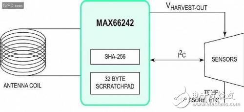
Figure 5. Schematic circuit diagram of a universal discrete sensor tag. MAX66242 Host I? The C port allows the smartphone to access the sensor and collect temperature data without the need for a microcontroller.
As described above, the sensor tag converts (or transforms) the analog physical quantity into a digital output. At this point, the MAX66242 is actually a bridge or conduit that connects these external analog parametric transformations with useful information that users can read on the screen of a smartphone or tablet. Similarly, the sensor tag using the IC does not require an external energy source, but uses its energy harvesting pin VOUT as the power source for the sensor IC. Figure 6 shows a schematic diagram of a typical discrete sensor tag.
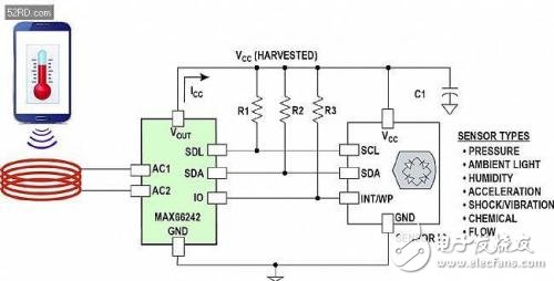
Figure 6. Discrete embedded sensor tag structure.
Diagnosing and erroneous data collection to solve long-term stability problemsIn short, the MAX66242 tag truly supports embedded systems to communicate with NFC-enabled portable communication devices. The NFC/RFID port also provides an alarm to the service personnel, similar to the "Immediate Service Engine" indicator on the car dashboard.
After implementing the circuit structure shown in Figure 4 in the embedded design, the system can exchange information wirelessly with the outside, including diagnostics and error checking, collecting data from failed circuits, operating status alarms, and other system configurations/ Debug and calibrate data. This flexibility provides OEMs with value-added features for end products.
Designers can use the MAX66242 to store diagnostic and fault data that is critical to system operation. This data can be uploaded after the system "hangs" or when it is not powered. This collection of system health and fault data is achieved through the interface of the NFC/RFID tag. Figure 7 shows a typical power management system where each point-of-load (POL) regulator is configured and monitored by a common power management bus (PMBus). PMBus is just I? A variant of the C bus. The critical operating parameters of each POL are continuously monitored during normal system operation. In continuous monitoring mode, the system manager can also perform corrective actions in response to a fault or a work alarm.
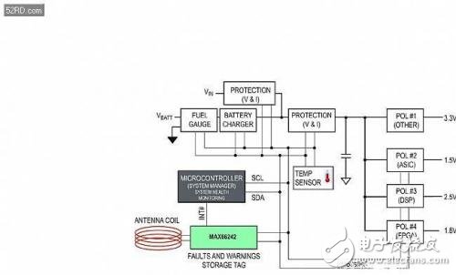
Figure 7. Block diagram of the power conversion system for fault logging with the MAX66242 NFC/RFID tag.
With the MAX66242 in this configuration, OEMs can create “bottles†or “black box flight recorders†that store over-capacity parameters (such as trigger point parameters for all monitored fault protection circuits). Now, technicians use RFID/NFC readers to read the measurements recorded before the failure occurred. This data can also be used to subsequently predict specific faults and help identify abnormal operating conditions. Additional intelligent diagnostic fault capabilities help predict, mitigate, and even eliminate the root causes of catastrophic failures in next-generation products.
Apply field sensors and I/O cards that are common in industrial control and automation. The MAX66242 tag allows the sensor card to be debugged while the device remains unpowered on the shelf. Simply download the analog calibration data, key parameters, or other system-level information to the tag on the sensor or I/O card using a smart phone prior to installation. Therefore, consumers can use their smart phones to purchase a specific device point card, then use a smart phone application (app) to load a point card, or activate the function through the NFC/RFID connection of the portable device.
to sum upIn recent years, the popularity of NFC/RFID technology has increased dramatically. But why add NFC/RFID to portable devices? Because this will open the embedded platform to more applications, it will spawn new and emerging secure portable communication applications; provide OEMs with excellent business opportunities. Undoubtedly, with the rapid development of this technology, potential applications are also increasing; NFC/RFID is considered to be one of the key cornerstones of IoT.
We present the NFC/RFIC application circuit with the DeepCoverMAX66242 security certification as the core. With this new approach, embedded portable systems are easy to connect to the outside world. OEMs can enhance their product differentiation. As smartphone and tablet manufacturers continue to add NFC/RFID technology to their products, the ecosystem will be gradually improved.
If everyone has an NFC/RFID reader, everyone can read some information. This is where OEMs come in and benefit again! The MAX66242 tag example provides designers with the flexibility to configure, securely authenticate, and report diagnostic data, and is the core of simple, clear implementation of NFC/RFID functionality in embedded systems. Taking action, most of the devices supporting NFC/RFID have not been implemented.
40 Port Usb Charger,Usb Power Strip,Multiple Usb Charger,40 Port Multiple Usb Chargers
shenzhen ns-idae technology co.,ltd , https://www.szbestchargers.com