When it comes to communication systems, differential circuits always provide better performance than single-ended circuits—they have higher linearity, anti-common-mode interference signal performance, and so on. The biggest challenge in using differential circuits is to abandon the idea that they are difficult to design, test, and calibrate, and you need to carefully observe how to use differential filters. Then the moderator asks, how to use a differential filter? Do you know how to cut?
I don't know, I will continue to look down. The moderator is simple and clear to tell you about the 8 points that need attention.
1. Pairs of differential traces must be the same length
This rule stems from the fact that the differential receiver detects the point at which the positive and negative signals cross each other, the crossover point. Therefore, the signal must arrive at the receiver at the same time to function properly.
2. The traces in the differential pair must be close to each other.
If the distance between adjacent lines in a pair is greater than twice the thickness of the dielectric, the coupling between them will be small. This rule is also based on the fact that the differential signals are equal but opposite, and if the external noise equally interferes with the two signals, their effects cancel each other out. Similarly, if the traces are routed side by side, any unwanted noise caused by the differential signal in adjacent conductors will be cancelled.
3. The spacing of the traces in the same differential pair must remain constant over the full length range.
If the differential traces are routed close to each other, they will affect the total impedance. If this spacing varies between the driver and the receiver, there will be an impedance mismatch along the way, causing reflections.
4, the spacing between differential pairs should be wider
To minimize crosstalk between them.
5. If copper is used on the same floor, increase the gap from the differential trace to the copper floor.
The recommended minimum gap is 3 times the width of the trace.
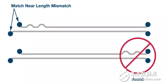
6. Correction of introducing a small amount of bending and bending at the source of the skew near the differential pair
Thereby reducing this skew.

7, differential pair wiring
Sharp turns (90°) should be avoided.

Symmetrical wiring should be used.

If test points are required, the introduction of trace branches should be avoided and the test points should be placed symmetrically).

8. Parasitic capacitance and electrical induction are as small as possible in terms of reducing the value of the filter component and reducing the amount of tuning work on the printed circuit board (PCB).
The parasitic inductance may be negligible compared to the inductor design value in the filter design. Parasitic capacitance is more important for differential IF filters. The capacitance in the IF filter design is only a few pF. If the parasitic capacitance reaches a few tenths of a pF, the filter response is considerably affected. To prevent parasitic capacitance effects, it is good practice to avoid any ground or power planes under the differential routing area and the power choke.
Brake Disc For ISUZU
ISUZU Brake Disc Replacement,ISUZU Auto Brake Disc,ISUZU Car Brake Disc,ISUZU Automobile Brake Disc
Zhoushan Shenying Filter Manufacture Co., Ltd. , https://www.renkenfilter.com