Summary:
Corrosion is serious for buried metal pipelines, and the assessment methods for cathodic protection in China are mostly manual inspections. The measurement data has large errors, incomplete data, and inconvenient viewing status. A remote collection system for cathodic protection data of metal pipelines is designed. A high-precision acquisition circuit was designed, and the cathodic protection parameters of the buried oil and gas pipeline were collected and sent back to the server through the GPRS/CDMA remote transmission method. Through the server to view the data and comprehensive analysis and processing of various data, obtain the current protection status of the protected pipeline, which provides an important basis for the protection of the pipeline. A dedicated power management module is designed to select the ultra-low power processor MSP430F5438 so that the current in the sleep mode is less than 20 μA, and the 12 000 mAh battery with solar cells can work for more than 10 years to make up for the shortage of field power supply.

0 Preface
At present, buried metal pipes are widely used in the transmission of oil, natural gas, and drinking water. Buried metal pipelines are buried underground for a long time, and due to different environments, different degrees of corrosion will occur [1]. According to statistical data, the direct economic losses caused by pipeline corrosion in China each year account for about 3% to 4% of the national economic net output value [2]. Corrosion, perforation and leakage of buried pipelines not only cause oil and gas leakage, but also cause disruption of transportation, causing huge economic losses. It also easily causes many safety problems and causes damage to the environment. Therefore, the protection of the pipeline is very important.
Cathodic protection mainly includes two methods: sacrificial anode method and external reinforcement current method [3]. Rectifiers are used in many countries to provide negative current protection, while China uses a combination of potentiostat and sacrificial anode to provide cathodic protection current. According to the current cathodic protection standard, the cathodic protection potential (tube/ground potential) should be between -850 mV and -1 200 mV [4]; when the above criteria are difficult to achieve, the cathodic polarization potential difference of the pipeline or The depolarization potential difference is greater than 100 mV as a criterion. China's oil and gas pipelines are extensively laid, and traditional manual inspection methods use multimeters and other instruments for on-site acquisition. The efficiency is low and errors are large. Only energized potentials can be collected, and the power-off potential at which the cathodic protection criteria is judged cannot be collected, resulting in a cathodic protection effect. Judgment error, and manual summary data in real-time, poor viewing and other inconvenient.
To sum up, it is necessary to develop a remote collection system for cathodic protection data of oil and gas pipelines for real-time viewing and management of cathodic protection data to evaluate the cathodic protection status of pipelines.
1 The overall structure of the system
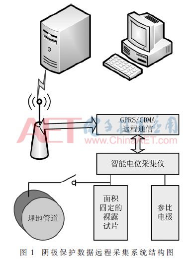
The structure of the cathodic protection data remote monitoring system is shown in Figure 1. It consists of a smart cathodic protection data acquisition instrument and a cathodic protection data management system. The intelligent cathodic protection data acquisition instrument will measure various parameters of the pipeline, including energization potential, power-off potential, alternating current potential, natural potential, direct current and alternating current. The data is transmitted remotely to the server's cathodic protection data acquisition and management system through the GPRS/CDMA wireless channel. The management personnel can use the PC login website to view the corresponding pipeline cathodic protection parameters.
2 Design of smart cathode protection data acquisition instrument
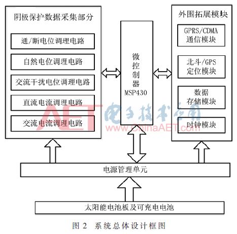
The intelligent over-insurance data acquisition instrument is mainly composed of a main control unit, a power management unit, a data acquisition and conditioning unit, a data storage unit, a GPS timing positioning unit, a clock unit, and a remote communication unit. Because the intelligent potential collector is applied to the field environment and requires high power consumption, the ultra-low power MSP430F5438 is selected as the processor of the main control unit [5]. The main parameters measured by the system are energization potential, power-off potential, AC interference potential, natural potential, DC current, and AC current. The system block diagram of the intelligent cathodic protection data acquisition instrument is shown in Figure 2.
2.1 The realization of the potential collection function
2.1.1 DC potential conditioning circuit
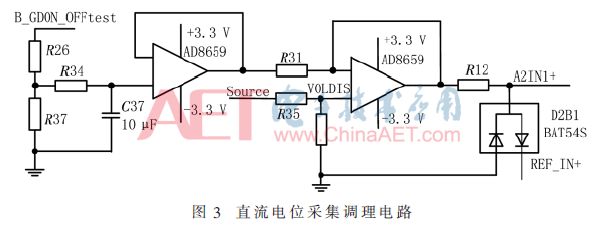
The DC circuit needs to measure the data including the energized potential, the disconnected potential, and the natural potential, and is divided into two channels of on-off potential and natural potential for acquisition. A four-channel, micropower, precision rail-to-rail input/output amplifier AD8659 is chosen. It has low supply current, low offset voltage, very low input bias current, and high immunity to electromagnetic interference. The precision of this device The combination of features applies to the high input impedance and anti-jamming measurements required in pipeline measurements. The analog-to-digital conversion chip used is the AD7705, which can acquire 0 to +2.5 V at a supply voltage of 3.3 V and a reference voltage of 2.5 V. According to actual requirements, it is necessary to collect voltage signals in the range of -5 V to +5 V, and the signal voltage range is changed to -1 V to + 1 V through a high-precision voltage dividing resistor, and then a voltage follower composed of a first-stage operational amplifier is used. In the second stage operational amplifier, the voltage rise 1.225 V becomes 0.225 V~+2.225 V, and then analog-digital conversion is performed to obtain the collection potential. The specific circuit is shown in FIG. 3 .
2.1.2 AC induced voltage regulation circuit
If there are transformers or high-voltage transmission lines near the buried pipeline, AC voltage will be coupled to the pipeline, causing AC corrosion [6]. Therefore, the AC voltage on the pipeline needs to be measured. As shown in Figure 4, the measuring end directly connected to the pipeline through the capacitor isolated DC signal, after the partial pressure into the half-wave rectifier circuit, and then enter the integration circuit in the capacitor C39 integration, through the MSP430's internal AD acquisition voltage according to the proportion of the current The AC voltage value that can be supported is an AC voltage with an effective value of 0 to +100 V.

2.2 The realization of current acquisition function
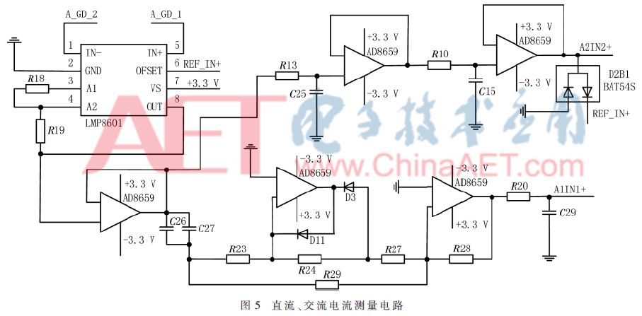
The cathodic protection current density in the pipeline refers to the protection current per unit area of ​​the pipeline to be protected, which is an important index to measure the insulation performance of the pipeline anti-corrosion coating [7-8]. This article designed a DC current measurement circuit and AC current measurement circuit. As shown in Figure 5, between A_GD1 and A_GD2 is a high precision 0.1 Ω sampling resistor connected in series between the pipe and the test strip. Use a bidirectional, voltage output current sense amplifier LMP8601 to pass the current through the high accuracy sampling resistor. Zoom in 20 times. A voltage follower composed of two stages of RC and op amp filters AC information, and measures the DC potential to obtain the current DC current. After the DC information is isolated by the capacitor, the AC signal is converted into a DC signal through a precision full-wave rectifier circuit. The AC is measured. The size of the current. Because the exposed area of ​​the test piece is fixed, the DC current density and the AC current density at the corresponding position of the pipe can be obtained.
2.3 Implementation of Beidou/GPS Time Synchronization Calibration Function
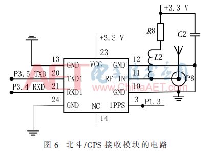
The time synchronization part uses the satellite clock as the synchronization reference [9]. The satellite receiver is a high-sensitivity Beidou/GPS dual-mode receiver ATGM332D. It supports GPS and BDS single-system positioning and dual-system joint positioning. Position information and time information can be received through the serial port, while the standard seconds pulse can be output on the TIMPULSE pin with an error of less than 1 μs. Because the calibration time of the clock chip is calibrated through the serial port, there is a large error. After the serial port timing is completed, the seconds pulse is used to generate an interrupt to calibrate the time. At the same time, after the measurement time is set for the measurement, the measurement interruption is turned on at 59 s one minute in the measurement time. Using the rising edge of the positioning chip second pulse as the start time of the interrupt measurement, the measurement time error can be reduced to within 1 ms. The Beidou/GPS receiver module circuit is shown in Figure 6.
2.4 Implementation of Remote Communication Functions
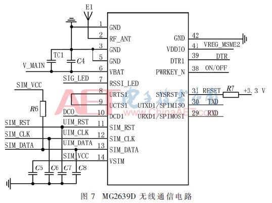
It is not convenient for wired communication to be used in the wilderness remote areas based on the use of a collection device, and it is decided to transmit information to the server using wireless communication. The GPRS/CDMA communication method has outstanding advantages such as low cost, wide access range, strong real-time performance, and no need to maintain links. The use of GPRS / CDMA communication can simultaneously support the domestic three major operators different SIM cards. The user can select the optimal traffic network according to the requirements, and design the communication unit as a communication board separately, and realize the connection with the main board through the pin. The MG2639D and MC8332D communication modules are selected to support the GPRS/CDMA two communication standards. The following uses the MG2639D as an example. As shown in Figure 7, the main control unit of the circuit MSP430 chip through the serial port to achieve communication with the MG2639, through the AT command to configure and control the module, through the SIM_RST, SIM_CLK, SIM_DATA three pins to complete the opening of the mobile / Unicom card Operation can realize data communication through GPRS network. Correspondingly, the communication method of CDMA only needs to replace the hardware with the MC8332D communication module and the telecommunication card, and the main program realizes the compatibility of various communication methods.
2.5 Low-power implementation
Because the intelligent over-insurance data acquisition instrument is working in the field for a long time, the replacement and maintenance of the power supply are very inconvenient. Therefore, the power consumption requirement of the system is very strict. In order to meet this requirement, the main processor and peripheral circuits of the acquisition instrument all use low-power chips. The ultra-low power TPS70933 is selected as the 3.3 V power management chip. The chip can be controlled by the EN pin. The power consumption in the shutdown mode is as low as 0.15 μA, and the power consumption in the operating mode is only 1 μA. The corresponding power supply needs to be turned on when the module is working. The collector is usually in sleep mode and will only be in work mode when working. The MSP4305438 has five power-saving modes, LPM0~LPM4, with a power consumption of 2 μA in LPM3 mode, which is the mode that supports the lowest power consumption that the interrupt can be awakened. After testing, only the master chip and the clock part work when the collector is in sleep mode, and the master chip is in LPM3 mode, and the whole system current is less than 20 μA. In the working mode, the average current of the cathodic protection data acquisition state is 30 mA, the acquisition time is about 20 s, the average current is 70 mA in the positioning timing and upload mode, and the required time is about 40 s. The system needs to collect 4 times a day. Information (3 measurements interference, 1 upload). The system uses 12 000 mAh rechargeable batteries in conjunction with solar panels. The system can work stably for more than 10 years.
3 System Workflow
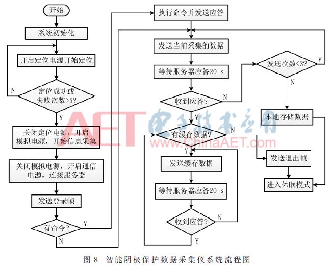
The system uses the ultra-low-power chip MSP4305438 as the main control chip, and in order to achieve low-power functions, power is supplied to different modules through multiple ultra-low-power power management chips. Only corresponding units are used in the program. Only supply power to it. At the same time, in order to ensure the reliable transmission of data, when the data is uploaded unsuccessfully, the data will be saved locally. Each upload checks whether there is cached data. If there is cached data, the cached data will be uploaded together. The specific workflow is shown in Figure 8. .
4 system function test
The functions of the long-distance collection system for the oil and gas pipelines were tested at the Tianjin Electronic Instrumentation Laboratory and passed inspections as required. An inspection report numbered TDYY No. 170081-WT was obtained.
4.1 Acquisition Instrument Measurement Accuracy
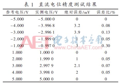
Taking the measurement of potential in the measurement as an example, a 6-digit digital multimeter 34401A is used, a program-controlled DC power supply AN50600SV1, and an intelligent frequency conversion power supply AN97005H. The measurement data are the average data after 3 measurements.
From the data in Table 1, the absolute error of the DC potential is no more than 4 mV, the error ratio is less than 0.30%, and the error ratio is less than 0.50%.
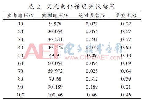
From the data in Table 2, it can be seen that the maximum error of the AC potential is 0.93%, which satisfies the requirement that the design error does not exceed 1%.
4.2 Functional Testing of Cathodic Protection Data Management Platform
Cathodic protection data management platform consists of gateways, databases, WebGIS-based websites [10]. The smart cathode protection parameter collector sends cathodic protection data to the server. The server sends the verified data to the database through the gateway as a transit station. After the pipeline administrator logs in through the website, he can view the parameters and related line charts.
The website of the cathodic protection management platform has set up data reports, management tools, user management, and expert systems. Pipeline managers can add, delete, modify, and query pipelines, pipe sections, and equipment through the management platform. The expert system can provide users with knowledge base and relevant pipeline maintenance suggestions. User management can set different levels of users to have different levels of operation and viewing rights. In the data report, you can view the data records of a certain collection point, or you can view all the data of all collection points of the entire pipeline on a certain day and generate a line chart to facilitate data analysis. The above functions were tested in Tianjin Electronic Instrument Research Institute.
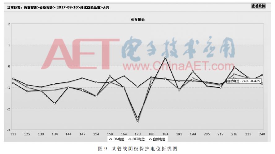
The system has now been applied to Beijing's refined oil pipelines, with a total of 40 cathodic protection parameter collectors. Figure 9 shows the line graph of the cathodic protection potential of the oil pipeline on a certain day. The potential anomaly at the 173 test point was found by looking at the power-off potential. Digging around the collection point revealed damage to the pipeline's anti-corrosion layer. Due to large external interference, the pipeline was maintained and the risk of pipeline damage was avoided.
5 Conclusion
In this paper, peripheral circuits such as the collection and conditioning circuit of different cathodic protection parameters and the synchronous positioning module are designed. An efficient, stable and energy-saving cathodic protection parameter remote monitoring system is designed through the wireless communication method of GPRS/CDMA, and the system will be protected. The various parameters are collected and sent back to the server. The server receives, parses, stores, and displays data, which facilitates pipeline managers to view the data and provides an important reference for the protected state of the pipeline. At the same time, it can obtain the current health status of the pipeline through a comprehensive analysis of various data of the pipeline. . All functions of the cathodic protection data acquisition system were tested at the Tianjin Electronic Instrumentation Laboratory and have been operating in a stable pipeline in Beijing. Practice has proved that this system has the characteristics of high precision, low power consumption, good stability, unattended, etc., to meet the design needs of field monitoring systems.
2000 puffs disposable vape pen are so convenient, portable, and small volume, you just need to take them
out of your pocket and take a puff, feel the cloud of smoke, and the fragrance of fruit surrounding you. It's so great.
We are China's leading manufacturer and supplier of disposable vape puff bars, 2000 puffs disposable vape,2000 puff vape pen,2000 puff e-cigarette kit
disposable vape 2000 puffs,2000 puffs vape kit, and e-cigarette kit, and we specialize in Disposable Vapes, e-cigarette vape pens, e-cigarette kits, etc.
2000 puffs disposable vape,2000 puff vape pen,2000 puff e-cigarette kit,disposable vape 2000 puffs,2000 puffs vape kit
Ningbo Autrends International Trade Co.,Ltd. , https://www.supermosvape.com