Design of vehicle communication platform based on DSRC
Carrying out research based on DSRC technology aims to provide a set of advanced means and scientific methods, which can comprehensively control, effectively carry out vehicle and driver assistance and traffic management, timely detect and find anomalies, reduce the occurrence of traffic accidents, improve driving and Transportation safety.
DSRC-based short-range communication (DSRC) technology for vehicle active safety technology is one of the foundations of ITS. DSRC system includes vehicle-road (V2R) communication and vehicle-vehicle (V2V) communication. Vehicle-road communication is the communication between vehicle and roadside infrastructure. It belongs to the communication between mobile nodes and fixed nodes. Ad Hoc network model; vehicle-to-vehicle communication is vehicle-to-vehicle communication, using the Ad Hoc network model based on multi-hop. The two communication methods are used in different fields.
1 Vehicle-Road Communication Vehicle-Road communication is mainly for non-security applications, represented by the ETC system. The vehicle passes through a specific ETC lane, communicates with the roadside RSU through the on-board OBU, and can automatically complete the charging process without parking and toll collection personnel to take any action. In addition, the DSRC application based on vehicle-road communication as shown in Figure 1 can also be used for downloading electronic maps and traffic scheduling. The roadside RSU is connected to the backup network and connected to the local traffic information network or the Internet. Through the communication between the OBU and RSU to obtain electronic maps and road condition information, the optimal route can be selected and traffic congestion can be alleviated.
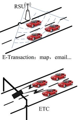
Figure 1 Application of DSRC in vehicle-road communication
2 Vehicle-to-vehicle communication The vehicle-to-vehicle communication method is mainly used for public safety of vehicles. Applying DSRC technology to the field of traffic safety can improve the safety factor of traffic. The role is to reduce traffic accidents, reduce direct and indirect economic losses, and reduce congestion on the ground transportation network. As shown in Figure 2, when a vehicle in front detects an obstacle or a car accident, it will send a collision warning message backward to alert the vehicle behind it of the potential danger.
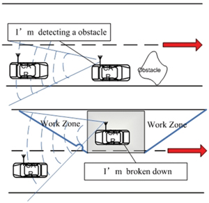
Figure 2 Application of DSRC in vehicle-to-vehicle communication
DSRC system network simulation research In order to analyze the network performance of the vehicle-mounted wireless communication system based on DSRC, a simulation method can be used. The simulation uses the traffic map of the Jiading campus of Tongji University, as shown in Figure 3. Suppose that a vehicle collides on a traffic road map, sends a crash emergency message, and the vehicle that receives the message interprets the message, controls its own vehicle, and continues to send the message to the surroundings and passes it to other related vehicles. The simulation is realized by MOVE software in combination with NS-2. It can be obtained through simulation that the data transmission delay of the DSRC system is less than 50ms, which meets the delay requirements of the vehicle environment. In order to achieve the best system performance, it is concluded through simulation that the system performance is optimal when the relative speed of the two vehicles is relatively small, and the size of the data packet is set to 200 bytes, and the transmission delay and throughput of the system Achieve the best balance and achieve the best characteristics of transmission performance.
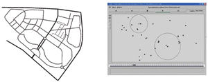
Figure 3 DSRC vehicle-mounted wireless communication system simulation scenario
Design of vehicle communication platform The establishment of vehicle communication platform is the preliminary exploration and attempt of DSRC technology. It consists of OBU and RSU. Figure 4 is a schematic diagram of the workshop communication platform. When the vehicle enters the service range of RSU, OBU can communicate with RSU Knowing the current road information, the video information of intersections, and the status of traffic lights, OBU can also communicate with each other to obtain the location and speed of surrounding vehicles to judge whether they will collide with each other, and warn drivers to prevent accidents. .
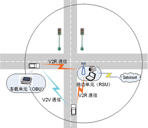
Figure 4 Workshop communication scene
Due to the small space in the car and the high requirements for communication delay, workshop communication puts forward higher requirements for the reliability and real-time performance of on-board equipment. This paper considers DSRC application scenarios and provides solutions for embedded on-board communication. Compared with the general-purpose computer platform, the DSRC embedded platform has the following characteristics in addition to its low power consumption and small footprint.
â— Stability In addition to meeting the high reliability of the transmission of safety messages, the actual circuit also needs to reduce glitches and interference, so that the system can still work stably and efficiently in the car and outdoor environments.
â— The real-time nature of the safety message transmission in the real-time workshop communication system needs to be less than 50ms, which puts forward higher requirements on the processing speed of the hardware chip and the operating efficiency of the software program.
â— The versatile workshop communication system is divided into roadside units and vehicle-mounted units. Devices of different manufacturers need to be interconnected, so compatibility between devices needs to be considered in hardware design and software protocols.
The on-board hardware platform system is shown in Figure 5. The wireless transceiver module will send or receive vehicle-to-vehicle or vehicle-to-road communication data packets. After processing by the on-board processor, the safety or non-safety information will be displayed on the user interface. If it is a safety message, it will also trigger an audio alarm to the driver Early warning. In addition, the GPS unit generates the safety message generated by the on-board processor and sends it to the neighboring vehicle through the wireless transceiver module.
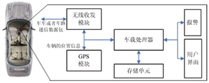
Figure 5 Overall framework of vehicle hardware platform
The wireless transceiver module is responsible for receiving and sending data according to the corresponding data format. Its structure is shown in Figure 6. Overall, the wireless transceiver module is composed of two parts: a radio frequency processing unit and a baseband / MAC processing unit. The GPS module outputs the longitude, latitude, and differential speed information of the current vehicle in a certain format through the serial port. The on-board processor will process and predict the current vehicle position and speed information received from the wireless transceiver module and GPS module. Determine whether there is a risk of collision.
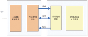
Figure 6 Wireless transceiver module structure diagram
The onboard processor selects the PXA270 with higher data processing capability and lower power consumption. The PXA270 processor is a processing chip based on the Intel XScale architecture, which integrates a storage unit controller, clock and power controller, DMA controller, LCD controller , AC97 controller and other peripheral controllers, can achieve rich peripheral interface functions. The PXA270 uses an ARM core and built-in Intel's wireless MMX technology, which can significantly improve processing performance and is suitable for in-vehicle information processing. Figure 7 shows the structure of the onboard processor. The memory chip uses two 64MB SDRAM models HYB25L256160AF and one 32MB Flash model K9F5608U0B-YCB0.
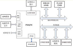
Figure 7 Structure diagram of on-board processor
For the vehicle-mounted unit, an operating system that can be tailored, has low resource occupation, low power consumption, and meets the requirements of real-time and multi-tasking at the same time is necessary. Among many operating systems, the embedded Linux operating system is a more appropriate choice.
Figure 8 provides the overall software design architecture of the vehicle-mounted unit, which is divided into five modules: video transmission module, data transmission module, data fusion processing module, GPS information acquisition module, and user interface module.

Figure 8 Software architecture of DSRC vehicle-mounted unit
The GPS information acquisition module receives the data from the GPS module through the serial port, and the user interface module is used to display the current status information of the vehicle. If necessary, an audio alarm is used to prompt the driver to pay attention to the current status.
The video and data transmission module is used to receive and send data packets. The received data packet first determines the type of the data packet. If it is video data, it is spliced ​​into a complete compressed frame. If it is non-video data, the data is unpacked. Direct delivery to the data processing module for processing. OBU judges whether the data packet expires by the time stamp in the data packet, and judges whether the video data is lost by the sequence number in the data packet. In video transmission, the data collected by the camera is compressed by MP4 and then transmitted according to the size of 1024 bytes. If a packet loss occurs at the receiving end, a frame of data is discarded accordingly.
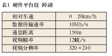
The function of the data processing module is to fuse the data information obtained by the GPS information acquisition module, the data transmission module, and the video transmission module and issue an alarm in time according to the information of the own vehicle and the location information of the surrounding vehicles. It uses Xvid open source codec library to perform MP4 decoding on the received video data and display the decoded image. Table 1 is the overall performance index of the workshop communication experiment platform.
Flat Control Cable Also known as festoon cable, this flat cable fits in confined spaces such as overhead cranes and hoists. It sends signal and data to operate, measure, or regulate automated equipment.
Raw cable can be UL2651, UL20251 ,etc
Flat cable, IDC cable, flat cable wiring, ribbon cable harness, flexible flat cable
ETOP WIREHARNESS LIMITED , https://www.etopwireharness.com