Frequency modulation wireless microphone circuit with voltage stabilizing circuit
To introduce you to a wireless microphone with a simple structure and a transmission distance of more than 200 meters. General beginners can make it successfully.
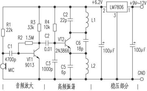
First, the circuit principle (see the following figure) The circuit consists of three parts: 1. Audio amplification part; 2. High frequency oscillation part; 3. Voltage regulation part. The signal is injected into the base of the transistor VT1 by the microphone MIC, and the audio signal amplified by VT1 is coupled to the base of the high-frequency oscillation circuit VT2 through C2, and then transmitted through the antenna. The operating frequency of this circuit is between 85 and 104MHz.
Second, the selection of components MIC selects a highly sensitive electret microphone, VT1 is 9013H, β≥125. VT2 is 2N3866; β≥90, ∮0.71mm enameled wire of L1 and L2 is closely wound on the ordinary ballpoint pen core by 4 turns and 10 turns, C4, C5 and C6 use ceramic capacitors, the error is ± 5%. The three-terminal regulator uses LM7806 power supply, 9V battery, and the circuit board can be self-made.
3. Assembly and debugging The circuit assembly is relatively simple, as long as the components are not damaged, one assembly can be successful. After the circuit is welded, the antenna is welded up again. The antenna uses a 0.5-meter radio antenna. Place the microphone at the sound source during debugging. Then, leave the microphone 5 to 6 meters away, turn on the FM radio, and adjust the channel selection knob. The turbid harmonics are received, and the pitch of the oscillating coil L1 can be adjusted with a screwdriver. The frequency increases when the pitch of the L1 is large, and vice versa. At this time, the received harmonic is not a sound.
If you want to increase the transmit power, you can change the length of the transmit antenna, or replace the VT2 launch tube with a 34D50 triode, and the R4 resistance with 4.7kΩ. At this time, the launch distance can be increased by about 100 meters. 
USB4 specifies tunneling of:
USB 3.2 ("Enhanced Superspeed") Tunneling
DisplayPort 1.4a -based Tunneling
PCI Express (PCIe)-based Tunneling
Main Benefits of USB 4
The new USB 4 standard has three main benefits over prior versions of USB.
40 Gbps Maximum Speed: By using two-lane cables, devices are able to operate at up to 40 Gbps, the same speed as Thunderbolt 3. The data is transmitted in two sets of four bidirectional lanes.
DisplayPort Alt Mode 2.0: USB 4 supports DisplayPort 2.0 over its alternative mode. DisplayPort 2.0 can support 8K resolution at 60 Hz with HDR10 color. DisplayPort 2.0 can use up to 80 Gbps, which is double the amount available to USB data, because it sends all the data in one direction (to the monitor) and can thus use all eight data lanes at once.
Better Resource Allocation for Video, PCIe: In lieu of alternative mode where the other interface takes over the connection, USB 4 devices can use a process called "protocol tunneling" that sends DisplayPort, PCIe and USB packets at the same time while allocating bandwidth accordingly.
Usb4 Cable,Usb To Usb4,Usb 4 Cable,Usb 4 Wires
UCOAX , https://www.jsucoax.com