The need for gamma correction stems from the invention of CRT television displays. The CRT uses an electron beam grating to illuminate the fluorescent coating behind the front panel of the display. The applied gate control voltage proportionally controls the intensity of the illumination and follows the law of illumination: the intensity of illumination = the gamma power of the control voltage. This control has inherent nonlinear properties. The nominal gamma value of the CRT is approximately 2.5. On the other hand, the human eye has a reverse response that is relatively sensitive to changes in the darker portions of the gray level. Therefore, in order for the final image to show a change in the true depth of the gray level to the human eye, the red, green, and blue signals must be gamma corrected before the image is transmitted. This correction is performed in a video source system, such as a television broadcast camera.
This article refers to the address: http://
This white paper describes how to ensure consistent brightness and color matching of automotive TFT-LCD panels through gamma correction (also known as gamma calibration). We will discuss how to use a 14-channel programmable gamma buffer to calibrate the gamma response of the LCD panel and introduce three examples of high, nominal, and low gamma settings.
The output voltage of the camera design is proportional to the luminous intensity, which is equal to 1/2.5 power (0.4 power) of the luminous intensity. Since gamma values ​​slightly larger than one are more favored, the broadcast standard typically uses a gamma of 0.5, resulting in a system gamma of 1.25. Figure 1 shows that the built-in gamma response of the camera is the reciprocal of the CRT response, so no additional system gamma correction is required. However, the TFT-LCD signal must be adjusted to compensate for the camera's gamma adjustment, which was originally set for the CRT display.

Figure 1. Gamma of a traditional CRT system
Automotive LCD panel gamma calibration <,strong>
TFT-LCD panels are increasingly used in automotive instrument clusters, infotainment and navigation body units, and advanced driver assistance system (ADAS) smart rearview mirrors. Instead of using an electron gun and a phosphor layer to produce luminescence intensity, they control the transmittance of the "backlight" through the pixel by applying a voltage to the liquid crystal pixel. A "cathode" is provided using a cold cathode fluorescent lamp (CCFL) or an array of light emitting diodes (LEDs). The voltage applied to the liquid crystal pixels can control the amount of backlight light transmitted to the front to reproduce the transmitted image, which can define a transmittance curve for the TFT-LCD.
The gamma value of a TFT-LCD is different from that of a CRT; however, it has a slight gamma response. The gamma calibration of a conventional broadcast system is performed during signal transmission to compensate for the CRT gamma response, and this combines the reverse response of the human eye. Therefore, the signal must be gamma corrected before it is applied to the TFT-LCD panel. TFT-LCD gamma correction is necessary to follow the gamma correction of the CRT display. The input video signal is digital and the gamma correction code is applied to a digital to analog converter (DAC) to generate a voltage and apply to the pixel. These gamma correction codes help panel display manufacturers determine the appropriate calibration code to meet visual effects requirements. The system is often able to store multiple gamma correction settings for different ambient light conditions. Figure 2 shows a normalized gamma correction for a TFT-LCD panel to achieve a system gamma value of one.

Figure 2. LCD system gamma
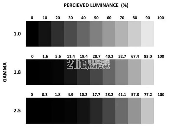
Digital video data, usually low voltage differential signaling (LVDS), must be converted using a DAC to produce an analog voltage applied to the pixel. Gamma correction (intentional nonlinearity) is performed using a piecewise nonlinear DAC in the source/column driver of the panel. The source driver DAC determines how many different voltage steps can be applied to the pixel (eg, an 8-bit DAC can produce 28 or 256 gray levels). Figure 3 shows the perception of gray level intensity variation caused by each voltage step, which is the gamma response (voltage-transmittance or VT curve) relative to the panel and the response of the eye.

Figure 3. Comparison of relative intensity changes for different gamma responses
The non-linear nature of gamma correction results in image data with low brightness levels being compressed, while image data with high brightness levels is compressed with little or no compression. Low-level compression makes the image data in the "dark" to "darker" areas more visible and more visible to the human eye. This can improve the image depth. As an added benefit, this compression and non-linearity results in lower numbers of bits used for luma coding (eg, 8-bit in the non-linear case and 12-bit or 14-bit in the linear case). In addition, compression can help reduce the noise of video signals that may be present.
Programmable gamma buffer
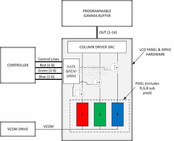
To change the gamma response of the LCD panel to the desired VT transfer function, the source (column) driver DAC of the panel can use various reference voltages applied to multiple tap points. These voltages force each DAC to have a specific ideal nonlinear operating condition. The reference voltage is often provided by a gamma buffer IC, typically a buffer amplifier that provides an analog voltage to the DAC tap point. The gamma buffer IC can be static or programmable. The Intersil ISL76534 is a device that can be used in automotive LCD panels. It consists of an I2C-based 14-channel programmable gamma buffer and a VCOM channel, both with a resolution of 10 bits. The device provides an accurate and stable DC reference voltage to automotive TFT-LCD source drivers. Figure 4 shows a simplified block diagram of a TFT-LCD panel system.

Figure 4. Simplified TFT-LCD panel block diagram
With control of the DAC tap points, automotive LCD panel manufacturers can fine tune the voltage to further adjust or calibrate the panel's nonlinear gamma response (also known as gamma calibration). This helps automotive LCD panel manufacturers ensure that all LCD panels of a certain model have a consistent gamma response. This means that potential visual effects differences caused by factors such as LCD manufacturing variations are minimized, so automotive LCD panel manufacturers are able to offer more consistent and visually appealing products. Consumers can be assured that the display of the car they purchased has the same visual effect as the one they saw at the dealer's test drive.
Finally, the panel manufacturer decides how to calibrate the gamma response (such as γ = 2.2, γ = 2.0, γ = 1.8, or a combination of different gamma values ​​based on the expected brightness) to give the display a specific visual effect. . It is worth noting that the gamma characteristic tends to change with the angle of view and different ambient lighting conditions. Therefore, when purchasing a car, you should compare the display effect of the display under strong light and low light conditions to determine whether the displayed image is You are satisfied.
Image comparison of different gamma values
Figure 5 compares the visual effects of the same image with different total gamma values, which is easy to see. The intermediate image (Fig. 5B) is the nominal (original) gamma value (eg γ = 2.2), the top image (Fig. 5A) is larger than the nominal value, and the bottom image (Fig. 5C) is smaller than the nominal value. The bottom image loses contrast as the dark color disappears and becomes a bit white. The contrast of the top image is larger, but there are more areas with darker overall.
Plastic Bluetooth Charger,Mobile Charger Wireless,Suction Cup Wireless Power Bank,Suction Power Bank
Shenzhen Konchang Electronic Technology Co.,Ltd , https://www.konchangs.com