The diode plays an important role in the rectification switch due to its unidirectional conduction characteristics; it acts as a voltage regulator in a certain current range in the reverse breakdown state. Surprisingly, the use of a diode's reverse bias junction capacitance can effectively reduce the access parasitic capacitance on the signal line. This application will be discussed further here.
Last time we shared our knowledge about how to use the diode's turn-on voltage drop. Later, users asked for more information about electronic devices. Here, we will talk about "how to use diodes to reduce parasitic capacitance."
Diode parameters - unidirectional conductivityReferring to the diode, the most familiar one is the unidirectional conductivity of the diode, which reflects the volt-ampere curve as shown in Figure 1. When the forward bias U=0.5V (silicon tube), the diode starts to conduct, the larger the current, the larger the voltage, the lower the impedance; when the reverse bias is applied, the diode does not conduct, and there is a certain range. Small leakage current with great impedance. Its unidirectional conductivity also acts as a switch, so it has a wide range of applications in rectification and switching.
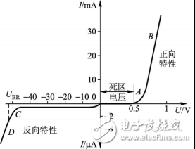
Figure 1 diode volt-ampere characteristic curve
Diodes have one parameter and are not as well known as unidirectional conductivity, but the impact on circuit design is also critical, that is, "junction capacitance."
Diode parameter - junction capacitanceIn some high-speed applications, it is necessary to select a diode with a relatively small capacitance; in some cases, it is necessary to use this junction capacitor for a specific purpose, such as a voltage controlled oscillator (VCO), which utilizes varactors in different There are different capacitance values ​​under reverse bias to achieve the purpose of voltage control frequency.
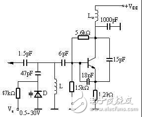
Figure 2 Voltage Controlled Oscillator Application Circuit - Example
On high-speed circuits, the effects of parasitic capacitance cannot be ignored due to higher and higher frequencies. In the system, these undesired capacitors come from all aspects, such as the material, thickness, layer structure, and parallelism of the PCB. These are the parasitic capacitances that affect the PCB, and the parasitic capacitance of the components themselves. The most hateful It is these things that are also affected by the ambient temperature.
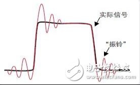
Figure 3 Parasitic capacitance causes "ringing"
Is there no way to deal with them? Through the unremitting efforts of engineers, it is found that these effects can be reduced by reasonable circuit design. Below we will discuss how to "use the capacitance characteristics of the diode to reduce the parasitic capacitance on high-speed signals" .
Diode magic - reduce parasitic capacitanceFirst, we are familiar with the capacitance characteristics of the lower diode: Figure 4 shows the capacitance characteristics of the IN4448HWS diode. Under zero reverse bias, the capacitance is 3pF, and as the reverse bias increases, the junction capacitance becomes smaller.
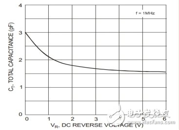
Figure 4 Capacitance characteristics
On high-speed signal lines, some functions are usually added. These functions usually have adverse effects, such as a large parasitic capacitance, which depends on the specific circuit module. If you ignore this capacitor, it may affect the frequency of this signal. The most unfortunate thing is that even if you notice this capacitor, it seems that there is nothing you can do because the capacitance generated by the additional function module is too large. The general attachment function access method is shown in Figure 5:
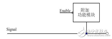
Figure 5 General Attachment Function Access Method
In order to reduce the parasitic capacitance on the signal line, a diode can be added at the access point of the accessory function. This diode must have a small junction capacitance. Usually, a small signal switch tube is used. If large current problems are considered, careful consideration should be given. Type problem.
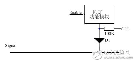
Figure 6 Forward Access Method
The forward access method is shown in Figure 6. The diode is connected between the signal line and the accessory function module, which means that the additional function module is high level when enabled. In addition, in order to reduce the parasitic capacitance to a greater extent, the diode is usually operated in a reverse bias state, that is, UL is connected to a low level. In the case that the additional function module does not work, the diode is at the maximum reverse bias voltage, has a smaller junction capacitance, and the signal line can operate at a high frequency state, and the system obtains higher performance.
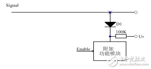
Figure 7 Reverse Access Method
The reverse access method is shown in Figure 7. Unlike the forward access, the positive pole of the diode is connected to the signal line, and UH is connected to the high level.
Regardless of the forward or reverse access method, the equivalent circuit is shown in Figure 8. We assume that the diode has a junction capacitance of 3pF and the accessory function module has a parasitic total capacitance of 1uF. If the resistance is large enough, it can be ignored. In this case, the two capacitors are connected in series, similar to the parallel connection of the resistors, CT=C1*C2/(C1+C2)≈C1 (C2 is larger). Even if the large capacitance changes greatly, the total capacitance in series is almost equal to the small capacitance, that is, 3pF, which effectively reduces the access capacitance.
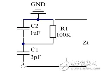
Figure 8 equivalent circuit
The above application is based on the unidirectional conductivity of the diode and the small junction capacitance. Forward access and reverse access can only be unidirectional, and cannot solve all situations, that is, only for special functional modules. If the additional function modules need to be bidirectional, combining Figure 6 with Figure 7 may be a good choice.
1200 Puffs Vape Pen,Pen Style Atomizer,Pen Atomizer,Vape Pen Atomizer
Shenzhen Xcool Vapor Technology Co.,Ltd , https://www.szxcoolvapor.com