The infrared automatic hand washing machine introduced in this example adopts pyroelectric infrared control technology, which can automatically open and discharge the water when the human body is close to the faucet; when the person leaves the faucet or the sigma leaves when the timing is over, the faucet will automatically close the water. The device is widely used in public places such as homes or hospitals, public health departments.
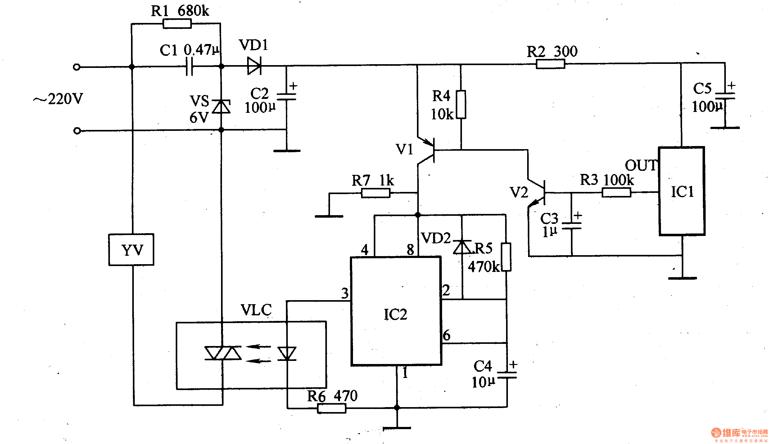
Circuit Operation Principle The infrared automatic hand washing circuit consists of a power supply circuit, an infrared detection control circuit and a control execution circuit, as shown in Figure 9-119.

The power supply circuit is composed of capacitors C1, C2, a resistor R1, a Zener diode VS, and a rectifier diode VD1.
The infrared detection control circuit is composed of a resistor R2-R7, a capacitor C3-C5, a diode VD2, a transistor Vl, V2, a pyroelectric infrared Sensor integrated circuit ICl and a time base integrated circuit IC2.
The control execution circuit is composed of an optical coupler VLC and a solenoid valve YV.
After the AC 220V voltage is stepped down by Cl, VS regulated, VD1 rectified and C2 filtered, 6V DC voltage is provided for the infrared detection control circuit.
Normally, Vl and V2 are in the off state, IC2 and VLC are not working, the internal light control thyristor is in the off state, and YV is in the off state. When the human body approaches lCl, the output terminal (OUT) of lCl will output a high level, so that V1 and V2 are saturated and turned on, IC2 is energized, and its 3 pin outputs a high level, so that the LED inside the VLC is lit, and the light control is performed. The thyristor is turned on, and the YV is energized to start discharging water. At the same time, C4 slowly discharges through R5, causing the voltage of pins 2 and 6 of IC2 to rise continuously. When the timing time is over (the 6-pin voltage of 1C2 rises above 4V), the circuit in IC2 is turned over, and the 3 pin outputs a low level, so that the circuit in VLC is turned off, and YV is powered off and stops working.
If the timing is not over, and the human body leaves IC1 a certain distance, the output of ICl goes low, so that Vl and V2 are turned off, and ICl and YV are powered off and stop working.
Changing the resistance of R5 or the capacity of C4 can change the length of the timing.
Component selection
Rl-R7 uses 1/4W metal film resistor or carbon film resistor.
Cl selects a CBB capacitor with a withstand voltage of 400V or higher; C2-C4 selects an aluminum electrolytic capacitor with a withstand voltage of 16V.
VDl selects 1N4007 type silicon rectifier diode; VD2 selects 1N4148 type silicon switch diode.
VS selects lW, 6.2V silicon steady voltage diode, such as 1N4735 and other models.
Vl selects S9013 or 3DG6 type silicon NPN transistor for use; V2 selects S8550 or 3DG8550 type silicon PNP transistor for use.
ICl selects SDO2 or P228, LN-206 and other pyroelectric infrared sensor integrated circuits; IC2 selects NE555 type time base integrated circuit.
VLC uses MOC3041 optocoupler.
YV selects D-1 type 220V electromagnetic water valve.
Circuit Operation Principle The infrared automatic hand washing circuit consists of a power supply circuit, an infrared detection control circuit and a control execution circuit, as shown in Figure 9-119.

The power supply circuit is composed of capacitors C1, C2, a resistor R1, a Zener diode VS, and a rectifier diode VD1.
The infrared detection control circuit is composed of a resistor R2-R7, a capacitor C3-C5, a diode VD2, a transistor Vl, V2, a pyroelectric infrared Sensor integrated circuit ICl and a time base integrated circuit IC2.
The control execution circuit is composed of an optical coupler VLC and a solenoid valve YV.
After the AC 220V voltage is stepped down by Cl, VS regulated, VD1 rectified and C2 filtered, 6V DC voltage is provided for the infrared detection control circuit.
Normally, Vl and V2 are in the off state, IC2 and VLC are not working, the internal light control thyristor is in the off state, and YV is in the off state. When the human body approaches lCl, the output terminal (OUT) of lCl will output a high level, so that V1 and V2 are saturated and turned on, IC2 is energized, and its 3 pin outputs a high level, so that the LED inside the VLC is lit, and the light control is performed. The thyristor is turned on, and the YV is energized to start discharging water. At the same time, C4 slowly discharges through R5, causing the voltage of pins 2 and 6 of IC2 to rise continuously. When the timing time is over (the 6-pin voltage of 1C2 rises above 4V), the circuit in IC2 is turned over, and the 3 pin outputs a low level, so that the circuit in VLC is turned off, and YV is powered off and stops working.
If the timing is not over, and the human body leaves IC1 a certain distance, the output of ICl goes low, so that Vl and V2 are turned off, and ICl and YV are powered off and stop working.
Changing the resistance of R5 or the capacity of C4 can change the length of the timing.
Component selection
Rl-R7 uses 1/4W metal film resistor or carbon film resistor.
Cl selects a CBB capacitor with a withstand voltage of 400V or higher; C2-C4 selects an aluminum electrolytic capacitor with a withstand voltage of 16V.
VDl selects 1N4007 type silicon rectifier diode; VD2 selects 1N4148 type silicon switch diode.
VS selects lW, 6.2V silicon steady voltage diode, such as 1N4735 and other models.
Vl selects S9013 or 3DG6 type silicon NPN transistor for use; V2 selects S8550 or 3DG8550 type silicon PNP transistor for use.
ICl selects SDO2 or P228, LN-206 and other pyroelectric infrared sensor integrated circuits; IC2 selects NE555 type time base integrated circuit.
VLC uses MOC3041 optocoupler.
YV selects D-1 type 220V electromagnetic water valve.
a thing that joins together two parts of sth, two vehicles or two pieces of equipment.

Custom Coupling,Coupling Of Encoders,Useful Coupling,Latest Coupling
Yuheng Optics Co., Ltd.(Changchun) , https://www.yhenoptics.com