Germany's DILAS new scanning galvanometer combines the advantages of coaxial temperature detectors in quasi-synchronous material surface temperature control and fast light scanning. The scanning galvanometer can be used not only in quasi-synchronous polymer welding, but also in some multi-solder reflow soldering that is not mechanically positioned in the same working surface. The temperature control process is stable and reliable during the welding process.
Pyrometer controlled laser process
Compared to other types of lasers, semiconductor lasers can convert energy (current) directly into laser radiation. Semiconductor lasers allow rapid adjustment of laser energy, which is critical for fast processing of closed-loop temperature control using pyrometers. In the case of polymer profile welding, welding and heat treatment, the pyrometer sensor can be integrated with the processing optics to detect coaxial heat radiation from the processing area.
In order to avoid mutual interference between the pyrometer and the laser source, the sensitive wavelength of the detector of the pyrometer must be different from the wavelength of the laser source. Pyrometers used in material processing mostly use highly sensitive detectors in the 1800 to 2100 nm wavelength range, while semiconductor lasers typically have a wavelength of 810 nm or 980 nm.
In order to determine the absolute temperature of the process, it is necessary to know some properties of the material, such as emissivity and surface characteristics. However, for most processes, these properties of the material are not determined. For example, in the soldering process, the state of the solder changes from a solid state to a liquid state and then back to a solid state, so the optical properties of the solder also change. During polymer welding, thermal radiation is absorbed or scattered by glass, pigment or other filler material.
For most applications, a corresponding temperature measurement is sufficient for open loop or closed loop process control. The pyrometer controller can store processing data such as soldering temperature and laser output power for archival and analysis purposes. Therefore, pyrometers are a useful tool for quality control and product development.
Scanning galvanometer and pyrometer
When it is desired to quickly position or move a laser spot, a common method is to use a scanning galvanometer. Typical applications are quasi-synchronous or reflow soldering of polymers. The mirror deflects the laser beam away from the optical axis of the lens and causes the beam to no longer be parallel to the optical axis. This has some serious consequences for the use of pyrometers. The optical properties of standard flat field lenses, such as focal lengths and anti-reflective coatings, can only operate in very small specific wavelength ranges. Because the pyrometer and the laser have different wavelengths, the chromatic aberration will cause the focus positions of the two to be different (see Figure 1). That is to say, during the processing, the radiation detected by the pyrometer is not from the focus of the laser. Thus, it is impossible to achieve a closed loop process or even temperature monitoring. However, by special design, a flat field lens that corrects chromatic aberration can be realized, so that the focus of the pyrometer and the laser coincide. Figure 2 shows the DILAS scanning galvanometer DL.S20P, which incorporates a monochromatic pyrometer and a flat field lens that corrects chromatic aberrations. The scanning galvanometer is used in conjunction with DILAS's COMPACT fiber-coupled semiconductor laser system, along with proven software for galvanometer and pyrometer control.
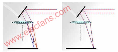
Figure 1: The pyrometer and laser have different focal points under a standard flat field lens (left), while the flat field lens (right) that corrects the chromatic aberration achieves a focus coincidence between the two. 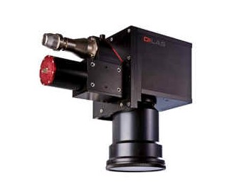
Figure 2: DILAS scanning galvanometer DL.S20P incorporates an axial monochromatic pyrometer for closed loop temperature control.
Quasi-synchronous welding
To test the characteristics of the weld, we designed a box-shaped test part, which is the most common in the automotive industry (see Figure 3). The lid is made of PBT (polybutylene terephthalate) doped with 30% glass. We use compressed air to break the box to check the quality of the weld. 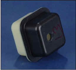
Figure 3: Laser welding test box
During the open loop process, the process temperature range is small. With a fixed welding speed, the laser power must be guaranteed to be ±2% stable in order to achieve a maximum breaking air pressure of approximately 11.2 Pa.
During the closed loop process, the processing temperature can be varied from 210 ° C to 280 ° C without much effect on the soldering results. The treatment temperature range was larger than during the open loop process and the failure gas pressure exceeded 11.7 Pa. In the measurement range of the pyrometer, the welding process is limited by the optical properties of the laser transmissive component. Transmission in the near infrared region determines the maximum welding speed that can be achieved. Scanning the galvanometer and correcting the working area of ​​the chromatic aberration flat field lens limits the size of the welded part.
welding
Laser welding with high-power semiconductor lasers, in addition to its advantages in electronics manufacturing, can also be used in thin-film solar cell soldering applications. Solder joints of several square millimeters can be obtained using continuous semiconductor laser welding (see Figure 4). Laser welding is a non-contact welding technique that provides precise heat dissipation and a very small heat affected zone. This limits the thermal stress generated by the solar cells during the soldering process.
Usually silicon solar cells are connected to each other in a thin line and then stacked in a module. This technique requires the use of additional equipment to handle long, fragile thin lines. With laser welding, it is possible to avoid the handling of thin wires by direct solder lamination. The stacking order of these modules is generally glass, polymeric ethylene vinyl acetate (EVA), tin-plated tape, solar cells, tin-plated tape, and transparent PVF underlayer (polyethylene compound fluoride). The front and back of the PV module are capable of transmitting laser light. Welding can be performed before or after lamination. Regarding the tensile force and contact resistance of the solder joint, the quality of the laser solder joint exceeds other connection techniques. The laser solder joint pulls three times higher than other methods, and the thermal resistance is only 14% of other methods [1].
There is no need to move the optical lens and the solar cell, and the scanning galvanometer can solder all the connection points on the solar cell module. Due to the limited working area of ​​the flat field lens, the scanning galvanometer must be moved to handle all of the modules.
Figure 5 shows the temperature versus laser power versus time for a closed loop weld. After the temperature rises for 150ms, it remains stable for 200ms to minimize thermal effects.
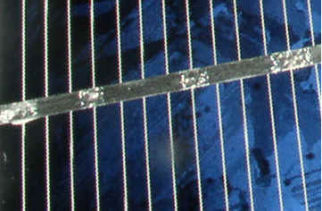
Figure 4: Laser welding in a solar cell module 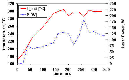
Figure 5: Temperature profile during closed loop welding
in conclusion
The use of fast-reacting laser sources and newly developed optics combines closed-loop pyrometer control with fast beam positioning with scanning galvanometers. The test results show a more stable welding process with a wider processing temperature range. This technology opens up a new processing method for industrial manufacturing that can significantly reduce the waste generated in production.
references
[1] W. Horn, High power Diode lassers for industrial ApplicaTIons, ICALEO (2007).
[2] E.jaeger, Diode lasers in Electronics and PlasTIcs ProducTIon, 6th Workshop ApplicaTIon of High Powr Diode lasers, Dresden Germany (2006)
48V25Ah Lithium Ion Battery,48V25Ah Lifepo4 Battery,48V Lithium Battery For Electric Scooter,48V25Ah Lithium Battery Pack
Jiangsu Zhitai New Energy Technology Co.,Ltd , https://www.ztbatteries.com