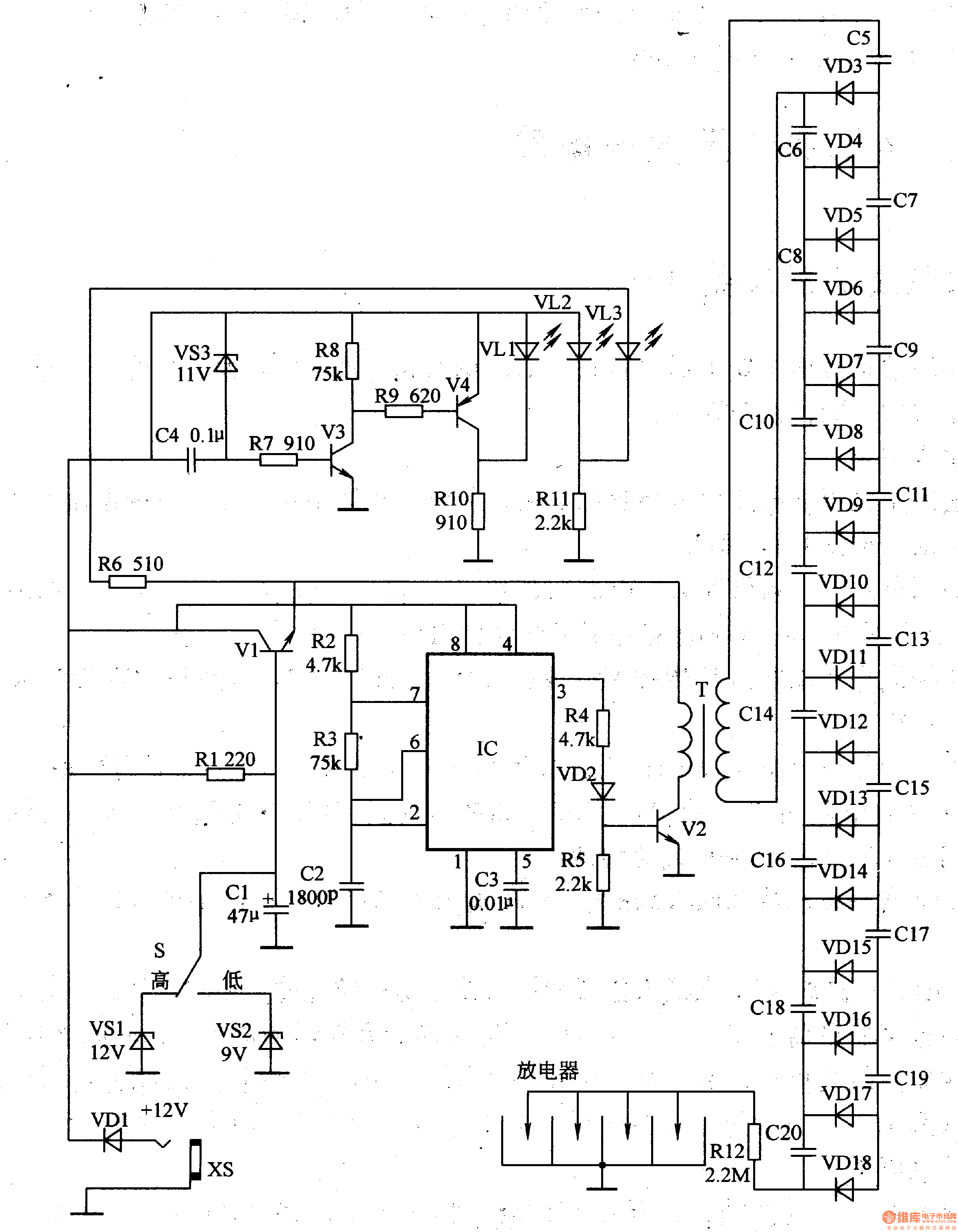
Circuit Operation Principle The negative oxygen ion generator circuit consists of a power supply voltage regulator circuit, an undervoltage detection indicating circuit, a high frequency oscillator, and a high voltage generator circuit, as shown in Figure 9-113.

The power voltage stabilizing circuit is composed of a diode VD1, a power adjusting tube Vl, a Zener diode VSl, a VS2, an ionization intensity selection switch S, a power indicating LED VL2, and a peripheral RC component.
The undervoltage detection indicating circuit is composed of transistors V3, V4, a Zener diode VS3, an undervoltage indicating LED VLl, and a peripheral RC element.
The high frequency oscillator is a metastable multivibrator composed of a time base integrated circuit IC and a peripheral RC element.
The high voltage generator circuit is composed of a resistor R4 and an embryo, a transistor V2, a boost pulse transformer T, a diode VD2-VDl8, a capacitor C5-C2O, and a discharger.
An external l2V DC power supply is input from the socket XS. VD1 is an isolation diode that prevents the positive and negative polarity of the input power supply from being reversed.
The +l2V voltage is directly supplied to the high-frequency oscillator via VDl, and the other is supplied to the high-voltage generator circuit after being stabilized by the voltage regulator circuit. After the high-frequency oscillator oscillates, the high-frequency square wave pulse signal is output from the 3 pin of the lC, and the control transistor V2 operates in the switch (alternating on and off) state, and a pulse high voltage is generated on the secondary side of the boosting pulse transformer T. After the high voltage is rectified by VD3-VDl8 and C5-C2O multi-stage voltage doubler, a DC voltage of nearly 10,000 volts is generated and applied to the discharger to ionize the air to generate negative oxygen ions.
The ionization intensity is high and low, and is controlled by the switch S. When S is placed in high-grade (High), l2V Zener diode VSl is connected to the circuit, and the high-voltage generator circuit is powered by high voltage. At this time, the voltage applied to the arrester is relatively high, and the air ionization intensity is also high; When placed in the low gear (Low), the 9V Zener diode VS2 is connected to the circuit, and the high voltage generator circuit is powered by a low voltage. At this time, the voltage applied to the arrester is relatively low, and the air ionization intensity is also low.
When the input voltage of +l2V is normal, the transistors V3 and V4 are both turned on, and the undervoltage indicates that the LED VLl does not emit light; when the voltage of +l2V is low to a certain value, both V3 and V4 are turned off, and VLl emits light, indicating the input voltage of the power supply. Low.
The power indicating LED VL2 emits light after being connected to the power supply, and the working indication LED VL3 emits light after the high frequency oscillator and the high voltage generator circuit operate.
Component selection
Rl-Rll selects 1/4W carbon membrane resistor for use; Rl2 selects 1/2W carbon membrane resistor or metal membrane resistor for use.
Cl uses aluminum electrolytic capacitors with a withstand voltage of 25V; C2 and C4 select monolithic capacitors; C3 selects aluminum electrolytic capacitors with a withstand voltage of 5OV; C5-C2O selects CBB capacitors with a withstand voltage of 15OOV.
Both VDl and VD2 use 1N4007 silicon rectifier diodes; VD3-VDl8 selects lW, l0OOV fast recovery rectifier diodes.
VLl-VU selects ordinary light-emitting diodes of φ5mm, in which VLl is red, VL2 is yellow, and VL3 is green.
VSl-VS3 selects IW silicon steady voltage diode, wherein VSl voltage regulation value is l2V, VD2 voltage regulation value is gV, VD3 voltage regulation value is 11V.
Vl and V3 select C1815 or C805O silicon NPN transistor for use; V4 selects AlO15 or C8550 silicon PNP transistor for V4; V2 selects 2SD2611 high frequency medium power tube or MJEl3003 Darlington tube for V2.
IC selects NE555 time base integrated circuit.
VooPoo Vape pen, Wholesale voopoo vape, VooPoo Disposable Vape
Shenzhen Xcool Vapor Technology Co.,Ltd , http://www.xcoolvapor.com