Ron Wilson, Altera Corporation
When it comes to the term “smart grid,†many people will first think of new types of electricity meters that have recently appeared outside their homes. However, ask a power engineer who will describe the most profound changes in power distribution since AC replaced DC. The smart grid brings the international grid from regional monitoring and local electromechanical control to an unknown new world of real-time, software-defined networks. In this article, we will briefly understand this immense change: the measurement and control network that connects the grid intelligence unit.
Development of the power grid
The world's power grid is not designed but gradually developed. In most regions, the grid is initially a point-to-point connection between the power plant and the load. The load may be a special large user, for example, a factory or tram power line, or a substation that distributes electricity to residents. The location of the power plant and the location of the user determine the topology of the network.
In the beginning, these connections are layered: the more energy that is transmitted, the longer the distance, the higher the voltage. The interfaces between different connection segments require switches, circuit breakers and transformers. Over time, these connections have evolved into a star topology where the substation is located at the center of each star, and then redundant links are added at higher levels.
The control network evolves with the power transmission network. Initially, it used mechanical switches; electromechanical meters were used for voltage, current, phase and volt-ampere reaction (VAR) measurements; controlled by personnel. Since people are not always able to react quickly to prevent damage to the network, the grid uses automatic circuit breakers at key points. With the development of technology, the network has added local smart devices such as telemeters, remote activation switches, central control rooms, and relays—circuit breakers will automatically shut down and restore the circuit in a timely manner.
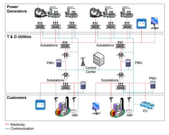
In the next phase of development, this patchwork network of smart local devices, telemeters, and remote controls has gradually evolved into an early smart grid (Figure 1). In some of the more remote areas, the substations buzzed and there was ozone smell. These places were the first to apply smart grids.

Figure 1. The smart grid enhances the measurement and control of power plants, distribution networks and power consumers.
Substation automation
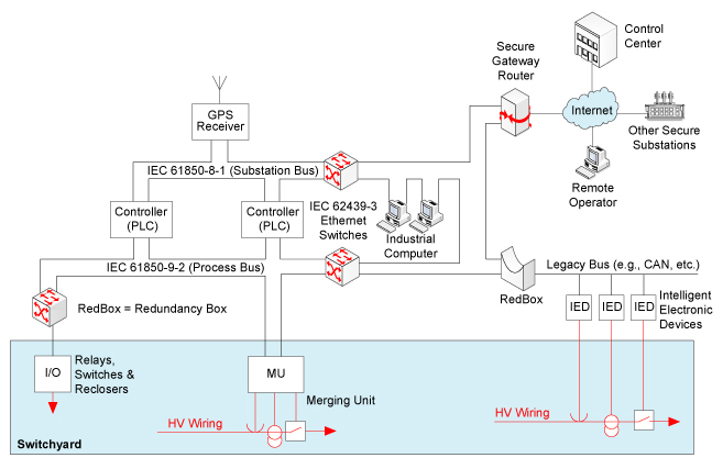
To some extent, the substation is like a microgrid enclosed by a fence. All the components of the grid are here - in addition to generators and users, including conductors, switches, circuit breakers, voltage regulators, power factor control and sensors, there are a large number of sensors. Until recently, all connections to these devices were point-to-point connections to the hub. The hub will connect to the control building and encode all the information to a dedicated microwave link or T1 line. The industry has found a good acronym for this automation: supervisory control and data acquisition (SCADA). All equipment is placed in one place, so substations can easily incorporate all equipment into a measurement and control network (Figure 2).

Figure 2. The substation has evolved to use a network for device interconnection.
In principle, the designer can connect all sensors, actuators and smart devices in the substation through an industrial Ethernet. Then, the local or remote server constantly evaluates the status of the substation and adjusts the control accordingly. However, the principle is very complicated when you need to quickly make certain responses that require compatibility issues between device vendors. To solve these problems, the industry has developed IEC 61850: Power Company Network Standards.
Of course, the standard establishes the foundation for interoperability and sets up a protocol stack for a local area network (LAN). It also sets response time requirements for key operations such as real-time data sampling and safety critical commands for obtaining circuit breakers. These requirements should leave enough space for the IEC 61850 compatible network to complete the data recording, switching and protection functions of the substation. However, these are not enough.
Network reliability
The network-based substation SCADA system may have broken connectors or failed transceivers that destroy the entire substation. This is of great concern. Correspondingly, power operators and equipment developers turned to network redundancy methods, and their ideas were implemented in another standard IEC 62439 high availability automatic network.
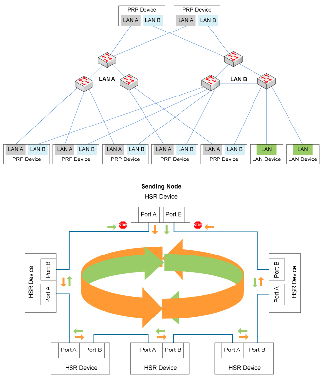
This standard is currently being amended to allow the convergence of two different redundant network schemes: Parallel Redundancy Protocol (PRP) and High-availability Seamless Redundancy (HSR) (Figure 3). The former standard sets a star topology with redundant switches, so each node has two paths, and the latter can use a star or bidirectional ring topology.

Figure 3. Different network topologies for PRP and HSR redundancy standards.
Two different topologies seem to be very good at achieving redundancy. However, Timo Koskiahde, chief technology officer of IP developer Flexibilis, pointed out that each has its advantages. The ring topology is more cost-effective because it does not require external switches. It also works well when the physical size of the network and the number of devices are limited. The binary topology can better adapt to large-scale networks and is easily updated from a single-star topology.
Koskiahde said that the update issue is very important, because many existing networks rely on the Spanning Tree Protocol (STP) or its Rapid Release (RSTP) to improve failure tolerance. These protocols attempt to reconfigure the network in the event of a link failure and, therefore, may not meet the zero error recovery time requirements of IEC 61850 in certain states. PRP and HSR transmit duplicate packets over two separate paths, so they can all satisfy zero recovery requirements.
Get Time
One of the fastest growing substations is measurement technology. At the beginning, substations controlled by people use electromechanical meters for measurements. After the introduction of SCADA, it is an electronic instrument - digital watch and position sensor, representing the current test technology of the substation. However, if these instruments are transferred from a dedicated merging unit to a network connection application, they will no longer be able to predict the time relationship between signals. This requires the data to be time-stamped to arrange the actual sequence of events.
Many substations have provided time reference via GPS receivers. However, how do you assign time stamps over the network? Many designers are turning to IEEE 1588 to solve this problem. IEEE 1588 distributes clock markings over Ethernet, using a training sequence to establish a delay between the reference clock and each receiving node of the network. In a stable LAN, IEEE 1588 can ensure that each node timestamps events with an accuracy of 1 μs or more and meets the requirements of IEC 61850.
Continuous development has enabled the substation to have redundant LAN functions, to achieve zero-time fault recovery, able to perform time-stamp measurements, and events with sufficient accuracy to control the system's use. These changes have been implemented, and power companies have also used smart meters in their customers to remotely monitor power usage at the point of use. The next step is to gradually merge these two approaches into a smart grid – a remote control substation and a distributed instrumentation network.
Smart grid
From the center-controlled substation network development to the smart grid theory, although simple, it actually covers a lot of content. Conceptually, the idea of ​​a smart grid is to network all sensors and actuators in a substation and extend them in multiple directions. These new directions include:
There are millions of sensors, switches, relays, and breakers distributed across a continent. New types of network connections are controlled by power generation equipment, controlled by new power supplies and loads, not just through distributed networks. New type of sensor New control algorithmThese new challenges have prompted the transformation of existing private networks in substations.
The first and most obvious change is the smart grid, which has a large number of nodes that cover a wide geographic area and cannot be managed by bridging existing private networks. It needs to use the Internet, not just the Internet backbone. In order to extend to independent power plants, circuit breakers in residential neighborhoods, rooftop solar panel controllers, smart meters, and electric vehicle charging equipment in homes, smart grid control networks need to use wireless and fixed networks, as well as public and private networks. Make a connection.
This change has a profound impact on the security of the power grid. It has been reported that people have been continuously detecting and attacking control networks through the Internet. Whereas smart grids use public infrastructure, these attacks will find new targets.
The industry has tried to predict what kind of challenges IEC 62351 will encounter. This standard provides authentication and intrusion detection, protection from illegal monitoring and deception. However, although the network is very good, only temporary emergency measures have been taken in these areas. As early as 2010, Anthony Metke and Randy Ekl and later Motorola discussed that only a fully public key encryption method can effectively protect the security of the power grid. Other experts cautioned that even this method is fragile in other applications. Only by continuous monitoring, active defense, or even the attack that will be launched can the security of the smart grid be realized. For network adapter designers, it is not always feasible to defend against threats. Therefore, for a growing city, the physical security depends on the functional power grid.
More advanced control
With more nodes and public networks, new types of nodes in smart grids are becoming more and more complex. For traditional large-scale and medium-scale power plants, the grid is now adding many small-scale solar facilities, and there are energy storage facilities in the future. With the gradual development of electric vehicles, a new type of atypical electricity consumption, new storage media, has begun to connect to the power grid. The addition of these things has changed the old way that electricity flows from the power plant to the user in one direction, and has a great impact on the impedance of the local branch. Since one of the main goals of the smart grid is to maintain dynamic stability—especially in response to accidental transient changes—the sudden change in impedance and current direction is a big problem.
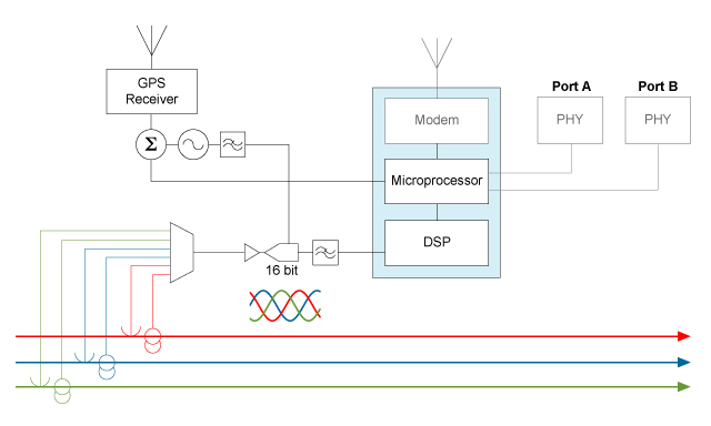
In this regard, power companies have expanded their sensor capabilities. One example is the more use of a phase measurement unit (PMU, Figure 4). These devices are actually slowly changing digital converters, typically 30 samples/sec. The PMU uses a GPS time reference to time stamp the samples. Therefore, in principle, the control center can understand the voltage, phase, and waveform at the same time through the network and support the accurate adjustment efficiency and power quality of the control center.

Figure 4. The modern PMU is a low-speed waveform digitizer with GPS time reference and redundant network connections.
However, this feature requires timestamping events at other nodes - relays, solar panel controllers, vehicle chargers, circuit breakers, and so on. Such a wide time protocol means not only millions of GPS receivers, but also IEEE 1588 on the public network.
Some conclusions
The smart grid network requirements of power plants or substations seem simple. The network must provide PRP or HSR redundancy. In practice, these requirements mean that the controller must have multiple network ports and protocol stacks to find replicated and compromised data packets at any time, delivering only the correct information to the application layer—zero latency.
Moreover, the network must comply with very stringent delay requirements for certain messages. GPS receivers, in conjunction with IEEE 1588, provide accurate time stamps for event reporting and data sampling. Vince Bridgers, senior employee and system planner of Altera's technical department, pointed out that IEEE 1588 also has its own difficulties. The network is periodically trained to establish an offset between the reference clock and the local clock. Many sources, including network topology, unexpected adapter or software delays, and PHY delays can cause jitter during training. Bridgers said that the approach is to provide a deterministic PHY of hardware time stamps, or use high priority message queues to bypass the delay in the protocol stack. However, network redundancy and very low jitter IEEE 1588 cannot coexist. Koskiahde said: "From the very beginning we needed to design IEEE 1588 support into redundant networks. We cannot add it to HSR or PRP later in the design process."
The biggest issue is the safety. A lot of work needs to be invested in implementing security systems, using cryptographic accelerators, trusted computing kernels, and tamper detection. However, incorporating redundant networks and low-latency, low-jitter messages into this environment will allow designers to enter a completely unfamiliar field.
Finally, extending the smart grid beyond the substation is also a challenge. This expansion has exacerbated all of the issues we discussed.
When the network is a public network, the concept of a zero recovery time redundant network immediately brings problems. If redundant connections can be used, are the offsets between the two different network connections small enough to allow failure recovery? Redundancy can compensate for the inevitable transmission delays of the Internet, or for devices outside the substation, the designer is Not to abandon the IEC 61850 requirements?
Similar problems exist in the public network IEEE 1588. Can power companies reduce GPS jitter by not placing GPS receivers on every node of the smart grid? Also, the security problems of so many nodes outside the power company's firewall? Can public key encryption be combined with a large number of intrusion prevention methods? Protecting the smart grid from intentional malicious attacks? Or, in the event of malicious attacks, grid system engineers can come up with effective control algorithms without guaranteeing transmission, delay, and jitter. There are still many final implementations of smart grids. The problem must be solved.
Winnowing Machine,Winnowing Rice,Seed Winnowing Machine,Grain Winnowing Machine
Hunan Furui Mechanical and Electrical Equipment Manufacturing Co., Ltd. , https://www.thresher.nl