UAVs have been widely used in police, urban management, agriculture, geology, meteorology, electric power and other fields. The flight control systems, pan/tilt and image transmission systems of drones are all key parts. What is the specific role of the UAV flight control system as its "brain"? What is it made up of? What issues should I pay attention to when designing?
The role of drone flight controlThe UAV flight control system refers to the control system that can stabilize the flight attitude of the UAV and control the autonomous or semi-autonomous flight of the UAV. It is the brain of the UAV and the most important sign that distinguishes it from the aircraft model. .
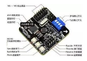
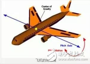
The control of fixed-wing UAV flight usually includes direction, aileron, lift, throttle, flap and other control rudder surface. The wing surface of the aircraft is changed by the steering gear to generate corresponding torque, and the aircraft turns, climbs, dive, and rolls. Wait for the action. However, with the development of intelligence, drones have emerged in various forms such as four-axis, six-axis, single-axis, and vector control.
The traditional helicopter-type drone controls the helicopter's slanting disc, throttle, rudder, etc. to control the aircraft's turn, climb, subduction, and roll. Multi-axle UAVs generally control the attitude of the drone by controlling the rotational speed of each shaft to achieve turning, climbing, subduction, and rolling. The role of the flight control is to control the drone through the gyroscope on the flight control board. Specifically, the four-axis flight state should be quickly adjusted. If the right side is found to be large and tilted to the left, then the right current output is weakened. The motor slows down and the lift becomes smaller, so it naturally no longer tilts to the left. If there is no flight control system, the four-axis aircraft will form an imbalance of flight forces due to installation, external disturbances, inconsistencies between parts, etc. The consequence is that the left and right, up and down, tumbling, can not fly.
UAV flight control work processThe flight control system collects the flight state data measured by each sensor in real time, and receives the control commands and data transmitted by the radio monitoring and control terminal from the uplink channel of the ground monitoring and control station. After calculation and processing, the control command is output to the executing mechanism to realize the UAV. Control of various flight modes and management and control of mission equipment; simultaneously transmit the status data of the drone and the operational status parameters of the engine, onboard power supply system and mission equipment to the onboard radio data terminal in real time, via radio The channel is sent back to the ground station.
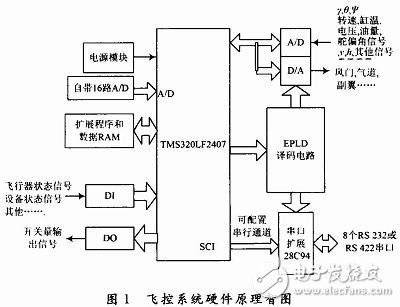
Flight control systemAccording to the function division, the hardware of the flight control system includes: a main control module, a signal conditioning and interface module, a data acquisition module, and a servo drive module.
The specific hardware structure principle is shown in Figure 1.


The various functional modules are combined to form the core of the flight control system, and the main control module is the core of the flight control system. It is combined with the signal conditioning module, the interface module and the servo drive module, and only needs to modify the software and simply change the peripheral circuit. Based on the requirements of a series of small UAV flight control and flight management functions, it can achieve one development, multiple models, and reduce system development costs.
The system mainly completes the following functions:

(1) Complete high-precision acquisition of multi-channel analog signals, including gyro signal, heading signal, rudder angle signal, engine speed, cylinder temperature signal, dynamic and static pressure sensor signal, power supply voltage signal, etc.
Due to the accuracy of the CPU's own A/D and the limited number of channels, an additional data acquisition circuit is used, the chip select and control signals are generated by the decoding circuit in the EPLD.
(2) The output switching signal, analog signal and PWM pulse signal can be adapted to the control requirements of different actuators (such as rudder, aileron servo, elevator, air passage and damper).
(3) Communication with onboard data terminals, GPS signals, digital sensors, and related task devices is realized by using a plurality of communication channels. Since the serial port configured by the CPU's own SCI channel cannot meet the system requirements, the design uses multiple serial port expansion chips 28C94 to expand 8 serial ports.
Kinetic Energy Materials,Friction Kinetic Energy,Gravitational Kinetic Energy,Materials That Absorb Kinetic Energy
Shaanxi Xinlong Metal Electro-mechanical Co., Ltd. , https://www.cnxlalloys.com