51 single-chip microcomputer is a basic microcontroller, or the most widely used one. This article mainly introduces 51 single-chip timer/counter, first introduced the working principle of 51 single-chip timer/counter, followed by 51 single-chip timer/counter working mode, and finally elaborated 51 single-chip timer/counter application, specific follow Xiaobian Get up and learn about it.
51 microcontroller timing/counter conceptIn the MCU, the relationship between pulse count and time is very close. Every time a pulse is input, the value of the counter will automatically accumulate 1. As long as the time interval between two adjacent count pulses is equal, the count value represents the time. As time goes by, the timers and counters in the SCM are actually the same physical electronic component, except that the counter records what is happening externally to the SCM (accepts external pulses), and the timer is provided by the SCM itself. Very stable counter, this stable counter is connected to the crystal oscillator component; MCS-51 microcontroller crystal oscillator after 12 divided by the stability pulse provided to the microcontroller; crystal frequency is very accurate, so the microcontroller count pulses between The time interval is also very accurate.
There are two sources of count pulses from the counter input, one is sent by the system clock oscillator output divided by 12; the other is an external pulse source input from the T0 or T1 pins.
When used as a timer, the timer counts the pulse count of the on-chip oscillator output of the 8051 after the frequency is divided by 12, ie, the register value of the timer T0/T1 is automatically incremented by one every machine cycle until it overflows and overflows. Continue counting cycles starting from 0; therefore, the resolution of the timer is 1/12 of the clock oscillation frequency;
When used as a counter, the external pulse signal is counted by the pin T0 (P3.4) or T1 (P3.5). When the input external pulse signal makes a negative transition from 1 to 0, the counter value is automatically The addition of 1 requires 2 machine cycles because of the detection of a falling edge from 1 to 0, so the level required to be sampled must be maintained for at least one machine cycle. When the crystal frequency is 12MHz, the maximum count frequency does not exceed 1/2MHz, ie, the count pulse period is greater than 2 microseconds. The highest frequency of the counter is generally 1/24 of the clock oscillation frequency;
It can be seen that neither the timer nor the counter operation mode, the timer T0 and T1 do not take up the CPU time, unless the timer/counter T0 and T1 overflow, it may cause CPU interrupt, and then go to execute the interrupt handler. Therefore, the timer/counter is a highly efficient and flexible component in the microcontroller.
51 single-chip timer working principle diagram:
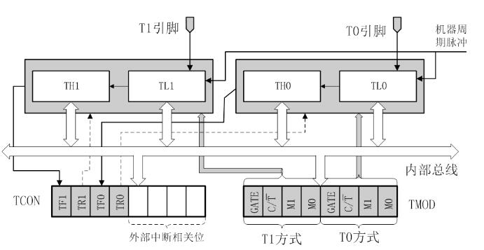
From the above figure, the timer-related registers are mainly the following: TMOD, TCON, TL0, TH0, TL1, and TH1. Here are some registers
16-bit addition counter:

The core of the timer counter, where TL0, TH0, is the bottom eight and high eight bits of the timer counter 0; TL1, TH1 are the bottom eight and high eight bits of the timer counter 1; and the high eight bits and the bottom eight bits may be separate use. The 16-bit addition counter is mainly used when setting the initial value of the timer counter
TMOD Timer Operation Mode and Mode Register

GATE: timing operation switch control bit, when GATE=1, the INT0 or INT1 pin is high, and the TR0 or TR1 control bit in TCON is 1 at the same time, the timer/counter 0 or 1 starts to work. If GATE = 0, Timer/Counter 0 or 1 starts operating as long as the TR0 or TR1 control bit is set to 1.
C/T: Select bits for the timer or counter function. C/T=1 is the counter, and the counting pulse is input through the external pin T0 or T1. Timer is C/T=0 and the internal system clock provides the timing pulse.
M1 M0: T0, T1 operating mode selection bits

TCON timer control register

TF1: Timer T1 overflow flag can be polled and cleared by the program. TF1 is also the interrupt request source. When the CPU responds to the T1 interrupt, it is cleared by hardware.
TF0: Timer T0 overflow flag can be queried and cleared by the program. TF0 is also the interrupt request source. When the CPU responds to T0 interrupt, it is cleared by hardware.
TR1: T1 allows count control bit. When it is 1, it allows T1 count (timing).
TR0: T0 allows count control bit. When it is 1, it allows T0 count (timing).
IE1: External interrupt 1 indicates the source (INT1, P3.3) flag. IE1=1, External interrupt 1 is requesting an interrupt from the CPU, which is cleared by hardware when the CPU responds to the interrupt.
IT1: External interrupt source 1 trigger mode control bit. This bit is set to 1 for the bottom level trigger and 0 for the falling edge trigger.
IE0: External interrupt 0 request source (INT0, P3.2) flag. IE0 = 1, external interrupt 1 is requesting an interrupt from the CPU, which is cleared by hardware when the CPU responds to the interrupt.
IT0: External interrupt source 0 trigger mode control bit. This bit is set to 1 for the bottom level trigger and 0 for the falling edge trigger.
51 single chip timer 4 working modesWorking mode 0:
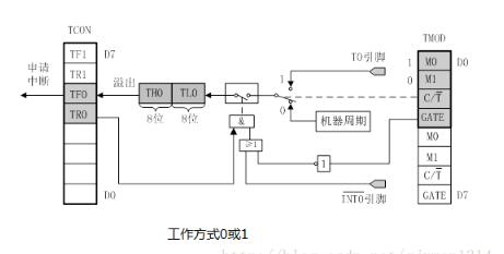
A 13-bit timer/counter is formed by the lower 5 bits of TL0 and all 8 bits of TH0. After the timer/counter is started, the number of timing or count pulses is added to TL0 from the preset initial value (time constant). ) Start accumulate, continue to increase 1, and when TL0 is full, it advances to TH0 until the 13-bit register overflows. When TH0 overflows, it sets the TF0 flag in TCON and sends an interrupt request to the CPU. And the timer/counter hardware will automatically clear the 13-bit register value to 0. If further timing/counting is required, it is necessary to use the relevant instruction to reset the time constant and set the timer/counter interrupt flag TF0 to zero.
Mode of operation 1: The most commonly used timer mode of operation
Mode 1 is almost exactly the same as Mode 0. The only difference is that the registers TH0 and TL0 in Mode 1 together form a 16-bit timer/counter to participate in the operation and therefore have a larger time/count range than Mode 0.
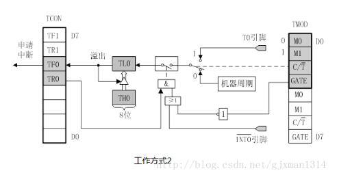
Mode of operation 2: Mode 2 is particularly suitable for use as a more accurate pulse generator.
This mode is also called automatic reload preset mode. Sometimes, our timing/counting operation needs to repeat the timing/counting multiple times. If there is no processing when overflowing, then in the second round of timing/counting, the timing/counting starts from 0, and this is not We want it. Therefore, to ensure that the operation of restarting the timer/counter after each overflow is what we want, it is necessary to reload the preset number (time constant) and reload the preset number of operations. It is the hardware equipment that finishes automatically, does not need manual intervention, so this kind of work pattern is called the automatic reloads the preset number way. In operation mode 2, the number of presets for automatic reloading is stored in the upper 8 bits of the timer/counter register, that is, stored in TH0, leaving only TL0 to participate in the timer/counter operation.
This mode of operation is commonly used in baud rate generators (serial communication), T1 works in serial mode 2; in this way, the timer is to provide a time reference; after counting overflow, there is no need to do too much, One thing you can do is to reload the preset number and start counting again without any delay in the middle.
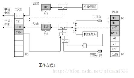
Working mode 3:
Mode 3 is only applicable to timer/counter T0. When timer T1 is in mode 3, it is equivalent to TR1=0. Stop counting. Since timer/counter T1 does not have operation mode 3, if timer/counter T0 is set to operation mode 3, then TL0 and TH0 will be split into two independent 8-bit timers/counters.
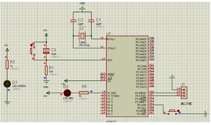
Create a simulation environment under protues:
Here's how to set the timer's initial value:
Working mode 0: 13-bit timer/counter operating mode, up to 2 of 13 times, ie 8192 times
Working mode 1: 16-bit timer/counter operating mode, up to 2 16 times, ie: 65536 times
Working mode 2: 8-bit timer/counter operating mode, up to 2 8 times, ie: 256 times
Working mode 3: 8-bit timer/counter operating mode, up to 2 8 times, ie: 256 times
Take the 12M crystal as an example: It can execute 1000000 machine cycle machine cycles per second. Each time the timer overflows up to 65536 machine cycles.
So for the 12MHz crystal oscillator
1 machine cycle 1us (12/fosc = 1us)
Mode 0 13-bit timer maximum time interval = 2^13 = 8.192ms
Mode 1 16-bit timer maximum time interval = 2^16 = 65.536ms
Mode 2 8-bit timer maximum time interval = 2^8 = 0.256ms = 256 us
Mode 3 8-bit timer maximum time interval = 2^8 = 0.256ms = 256 us
The above is a description of the timer maximum time interval. The following details how to calculate the initial value (less than the maximum time interval) If the timer 10ms then the initial value of the timer is calculated as follows:
- When using a 12M crystal oscillator, 12MHz divides 12 into 1MHz, that is to say one second = 1000000 machine cycles. 10ms = 10000 machine cycles.
The calculation formula of the preset number: preset number = maximum value - number of times to be counted; (65536-10000)
Then load the preset number into the 16-bit timer counter as follows:
TH0=(65536-10000)/256
TL0=(65536-10000)%256
- When using a 11.0592M crystal oscillator, 11.5922 MHz divides 12 into 921600 Hz, which is 921.6 machine cycles per second and 10 ms = 9216 machine cycles.
The formula for calculating the preset number: preset number = maximum value - number of times to be counted; (65536-9216)
Then load the preset number into the 16-bit timer counter as follows:
TH0=(65536-9216)/256
TL0=(65536-9216)%256
After the introduction of the initial value determination, the following describes the two most common usage of the timer
Timing: The timer counter is used as a timer. The configuration steps are as follows:
1. Mode settings, configure the TMOD register
2. Timer initial value setting assumes 10ms interrupt
3 open timer interrupt
4. Total open interrupt
5. Turn on the timer
Through the above 5 steps to open a timer, the timer did not initiate an interrupt 10 milliseconds, that is not 10 milliseconds to enter an interrupt service routine
The sample program is as follows:
#include"reg51.h"
Sbit led=P1^0;
Unsigned int flag;
Void main()
{
TMOD = 0x01;//1. Mode setting, 00000001, using timer 0, working with formula 1 (M1=0, M0=1).
TH0=(65536-10000)/256; //2. Timer setting, initiate an interrupt every 10 milliseconds.
TL0=(65536-10000)%256;
ET0=1; //3. On timer 0 interrupt
EA = 1; //4. Open total interrupt
TR0=1; //5. Turn on the timer
While(1)
{
If(flag==100)
{
Led=~led;
Flag=0;
}
}
}
Void TIM0() interrupt 1 //Interrupt service routine
{
TH0 = (65536-10000) / 256; / / enter the interrupt to reset the timer to deal with, pay attention.
TL0=(65536-10000)%256;
Flag++;
}1234567891011121314151617181920212223242526272829
Counting: The timer counter is used as a counter. The configuration steps are as follows:
1. Mode settings, configure the TMOD register.
2 open counter interrupt
3. Total open interrupt
4. Turn on the counter
Through this simple four steps, we have opened a counter that can perform pulse counting on the falling edge of P3.4 or P3.5. There is one thing to note here is that the counter can not open the interrupt, so that it will not interrupt when it overflows. Service program.
The sample program is as follows:
#include"reg51.h"
Sbit led=P1^0;
Sbit s=P3^4;
Unsigned int count;
Void main()
{
TMOD=0x05; //1. Mode setting, 00000101, using counter 0, working mode 1 (M1=0, M0=1).
TH0=0; //The counter is cleared
TL0=0;
ET0=1; //2. Open counter 0 interrupt
EA=1; //3. Open total interrupt
TR0=1; //4. Turn on the counter
Led=1;
While(1)
{
Count=(TH0 ""8)|TL0;
If((count*10000)==50000) // Press the 5 button to invert the status of the led
{
Led=0;
TH0=0XFF;
TL0 = 0xFF; // artificially put the counter into the interrupt
}
}
}
Void TIM0() interrupt 1 //Interrupt service routine
{
Led=1;
TH0=0;
TL0=0;
}
15.6 inch Laptop is one of the most important sizes on the market, more than 85% clients choose this size for business, teachers, middle or high school students, university students projects. 15.6 inch Gaming Laptop is ranking the first level of custom laptop, you can see i5 15.6 inch laptop, intel celeron n5095 Cheap 15.6 Inch Laptop, i7 11th 15.6 Inch Laptop In cm, etc.
15inch gaming Laptop with 11th Gen Intel Core i5-1135G7 processor ( up to 4.2GHZ, 4core, 8threads, 8MB caches) or 15.6 inch i7 1165G7 8 512gb Solid State Drive laptop ( up to 4.7GHZ, 4core, 8threads, 12MB Caches) should attractive your eyes when choose a competitive and hot gaming laptop.
Of course, other parameters levels, like 14 inch n4020 64gb laptop for online classes, 10.1 Inch Laptop equipped with 64gb rom, android 11 or windows 10 , or 11 Inch Windows Laptop in metal with 360 rotating, celeron quad core cpu, etc.
Except, 8 inch Android Tablet, Mini PC host, All In One Desktop also available here. So just share your idea about what you exactly need, then we do following for you.
15.6 Inch Laptop,15.6 Inch Gaming Laptop,15.6 Inch Laptop In Cm,I5 15.6 Inch Laptop,Cheap 15.6 Inch Laptop
Henan Shuyi Electronics Co., Ltd. , https://www.sycustomelectronics.com