Abstract : In order to reduce the construction and operation cost of urban parking guidance system, a system architecture without establishing a management control center is proposed. LPC11C14 and CC2530 are used as core chips to design an important part of the system-regional Zigbee network. Through the experiment of the developed test system, it shows that the Zigbee network can accurately receive the parking request from the user's mobile phone, and can feedback the optimal parking space information to the user according to the parking space status in the parking lot, from the user sending the request to receiving the feedback information. The time does not exceed 10 s.
This article refers to the address: http://
The parking guidance system is a multi-level information release as a carrier, which can provide information such as the location of the parking lot, the number of parking spaces, and the status of the parking space in real time, and guide the driver to effectively stop the information system. According to the size of the coverage, the parking guidance system can be divided into two types: urban level and parking lot level. In order to save the construction and operation cost of the city-level parking guidance system, this paper proposes a system architecture that does not need to establish a management control center. On this basis, this paper focuses on the hardware and software design of the regional Zigbee network, an important part of the architecture.
1 Research status
The parking guidance system is an intelligent transportation system for alleviating the difficulty of parking in the city. Aachen, Germany, first appeared in 1971 in Germany, and its development effect has been remarkable in the past 40 years. The construction of China has started in 2001, and the development of nearly 10 years has also achieved good results. After analysis, it is found that although various systems at home and abroad have their own characteristics, their system structure and working principle are basically similar, which are roughly composed of data acquisition, data transmission, central management and data release. Therefore, it is necessary to construct and maintain a city-level management and control center. The operation department also needs to pay the communication fee between the two parts of data collection and data release and the management control center for a long time, resulting in higher cost of system construction and later operation.
2 system overall architecture
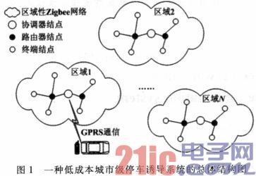
By deploying a “regional†ZigBee network in each indoor parking lot in the city, in each outdoor parking lot, and in each roadside parking area, and in conjunction with the parking user’s smartphone, it can be completed throughout the city. Achieve parking-inducing functions. In the above architecture, there is no need to build a city-level management control center, which can greatly save system construction and post-operation costs. The designed system architecture is shown in Figure 1. The general workflow is:
1) All terminal nodes of each ZigBee network periodically collect parking space status information from connected sensors.
2) If the collected parking space status is different from the previous state, the current parking space status is sent to the adjacent router node and waits for feedback from the coordinator node. If feedback is not received after a certain period of time, it will be resent until feedback is received.
3) Each router node forwards the received data of the terminal node to the coordinator node.
4) After receiving the message of the change of the parking space status, the coordinator node sends feedback to the terminal node and updates the database.
5) When the car travels to a certain place, the user triggers the smart phone to make a request for finding a parking space, and the pre-installed smart phone software runs the parking lot optimization algorithm according to the current position of the vehicle to determine the optimal parking lot (or roadside parking area). .
6) The smartphone software communicates with the coordinator node of the optimal parking lot (or roadside parking area), and the coordinator node queries the current parking space status database. If there is no free parking space, all the information that the parking space is full is fed back to the smartphone software; otherwise, the system runs the parking space optimization algorithm to determine the optimal parking space.
7) After determining the optimal parking space, the smartphone software first directs the vehicle to the destination parking lot (or roadside parking area). Continue to guide the vehicle to the destination parking space.
3 Hardware design of regional Zigbee network
A regional Zigbee network consists of three types of nodes: coordinator, router, and terminal. The terminal node is responsible for periodically collecting the parking space status and transmitting the information of the parking space state change; the router node is responsible for forwarding the parking space state change information; the tasks of the coordinator node include: receiving the parking space state change information and updating the database, and receiving the user through the smart phone. The parking request is issued, the parking space status in the database is checked, the parking space optimization algorithm is run, and the optimal parking space information is fed back to the user.
In the coordinator node, the following main components are required: 1) an embedded controller chip for managing the embedded database; 2) a Zigbee communication chip for communicating with the router node; 3) a GPRS module, Communicate with the user's smartphone.
The embedded controller uses NPC's LPC11C14 chip. The chip uses the Cortex-M0 core processor and operates up to 50 MHz. In terms of memory, 32kB FLASH and 8KB SRAM are configured; in terms of interface, there is a serial port, a 2-channel 10-bit ADC, two SPI interfaces, an I2C interface, and a SWD interface.
Zigbee communication chip uses CC2530 of n company. The chip is suitable for applications such as 2.4 GHz IEEE 802.15.4 and Zigbee. The chip includes RF transceiver, programmable flash memory, enhanced 8051MCU, 8KB RAM and so on. Since the time to transition from sleep mode to active mode is very short, the chip is particularly well suited for low power applications.
Since the LPC11C14 chip does not contain EEPROM internally, in order to realize the storage of the parking space status data in the embedded database, the AT24C02 chip is externally connected through the I2C interface. The communication between the LPC11C14 and the CC2530 is designed to communicate using the serial port. Because LPC11C14 only has one serial port resource, in order to realize the serial communication between LPC11C14 and GPRS module, SPI to serial port chip MAX3100 is used for conversion.
The GPRS module uses the universal module SIM_300S. The power chip of the LPC11C14 board uses the MIC5209, and the power chip of the CC2530 board uses the HT7533. The overall hardware block diagram of the coordinator node is shown in Figure 2.
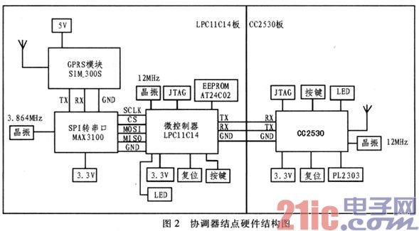
The hardware block diagram of the terminal node and router node is very similar to the block diagram of the CC2530 in the coordinator node. The difference is mainly that the parking space detection sensor is connected to the terminal node, and the terminal node and the router node are powered by a lithium Battery.
4 Software design of regional Zigbee network
The main program flow chart of LPC11C14 in the coordinator node is shown in Figure 3. Initialization is completed first after power-on. If the parking status change information sent by CC2530 is received, feedback is sent to CC2530, and the database is updated. If a parking request is received, it is determined whether there is an available parking space based on the current state of the parking space in the database. If there is an idle parking space, run the parking space optimization algorithm to determine the optimal parking space. After that, the results are fed back to the user via the GPRS module.
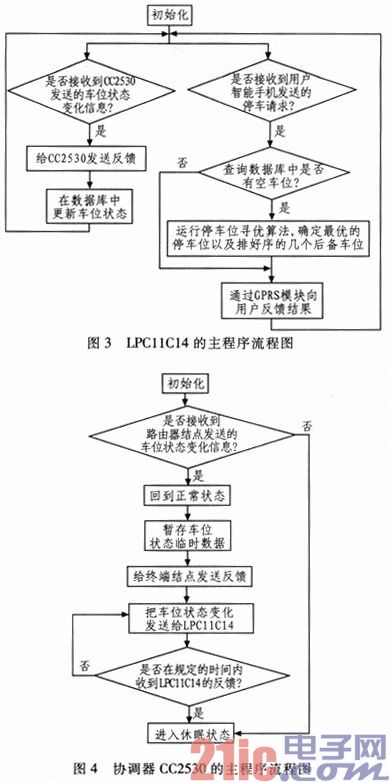
The main program flow chart of CC2530 in the coordinator node is shown in Figure 4. After initialization, it is first determined whether a parking space status change message is received. If not received, enter the sleep state; if received, return from the sleep state to the normal state. Next, in order to prevent the parking space state from being lost to the database, it needs to be temporarily stored in the flash memory inside the CC2530. After that, feedback is sent to the terminal node through the router node. Finally, the parking space change information is sent to the LPC11C14 and waiting for feedback. If no feedback is received within the specified time, it will be resent; if feedback is received, it will enter the sleep state.
The main program flow chart of the terminal node is shown in Figure 5. After the initialization, the data is collected for the parking space detection sensor, and the obtained data is AD-converted by the A/D module provided by the CC2530, and then stored in the FLASH inside the CC3530 in a loop coverage manner. After that, it is judged whether the current state is the same as the previous state. If the parking status changes, the Zigbee RF module sends data to the coordinator node through the router node and waits for feedback from the coordinator node. If the feedback of the coordinator node is not received within the specified time, the data is retransmitted; if the feedback is received, the timer interrupt is turned on and then enters the sleep state. Next, wait for the timer interrupt to wake up and proceed to the next data acquisition.

The main program flow chart of the router node is shown in Figure 6. If the parking space status change information sent by the terminal node is received, an external interrupt is generated, and the sleep state returns to the normal state. Then it is stored in the FLASH inside the CC3530 in a loop coverage. The information on the status change of the parking space is then sent to the coordinator node and waits for feedback from the coordinator node. If no feedback is received within the specified time, retransmission is performed; otherwise, the feedback sent by the coordinator node is forwarded to the terminal node, and then enters the sleep state, waiting for the external interrupt to wake up.
5 physical display and simulation results
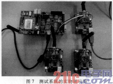
Figure 7 is a physical representation of the developed test system. In the upper middle of Figure 7, the left side is the LPC11C14 board of the coordinator node, and the right side is the CC2530 board of the coordinator node. In the LPC11 C14 board, the part with the antenna on the left is a commercial GPRS module. In the CC2530 board, the upper part of the antenna with the antenna is a commercial Zigbee RF module. Since the frequencies of these two parts are in the microwave frequency band, commercial mature modules are used to ensure reliability. In the lower middle of Figure 7, the left side is the router node and the right side is the terminal node. In order to ensure the test results, the two nodes are tested with a commercial Zigbee module. After the test is passed, the backplane can be replaced with the backplane developed by itself (ie, the backplane used for the CC2530 board in the current coordinator node). .
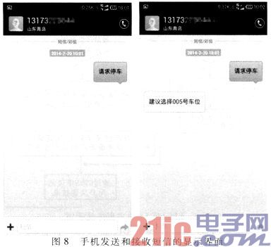
In order to test the effectiveness of the regional Zigbee network software and hardware design, the test data shown in Table 1 is stored in the embedded database of the LPC11C14 board in advance. After that, the mobile phone sends a text message to the GPRS module of the LPC11C14 board to make a parking request. Next, the LPC11C14 runs the parking space optimization algorithm. According to the data in Table 1, after calculation, it is concluded that the parking space No. 005 is the best. Then, the GPRS module of the LPC11C14 replies to the mobile phone with a text message. The sending and receiving interface of the short message is shown in Figure 8. According to the timing result, the time from the trigger of the SMS send button to the receipt of the feedback does not exceed 10 seconds.
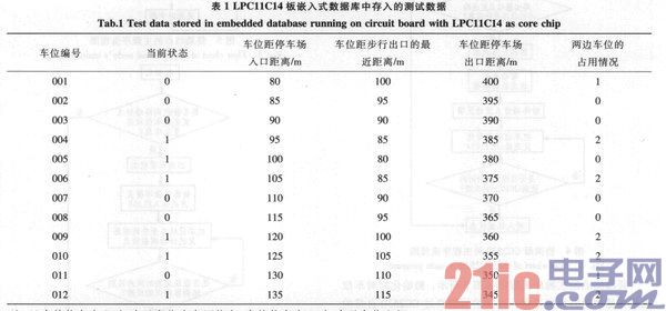
Note: 1) When the current status is 0, it indicates that the parking space is occupied; when the current status is 1, it indicates that the parking space is idle. 2) When the occupancy of the two parking spaces is 0, it means that the parking spaces on both sides are unoccupied; when it is 1, it means that one side is occupied; when it is 2, it means that both sides are occupied.
6 Conclusion
With the embedded chip LPC11C14 and Zigbee communication chip CC2530 as the main components, a set of hardware circuits for parking induced regional Zigbee network is designed. At the same time, the control and communication procedures of the three types of nodes of coordinator, router and terminal are developed. Test experiments show that the designed Zigbee network can accurately receive the user's parking request, and can timely feedback the best parking space information, from the user request to the receipt of feedback for less than 10 s.
Acid Filling Machine,Battery Acid Filling Machine,Acid Filling Machine Battery,Quality Acid Filling Machine
Zhijiang BSL battery technology service company , https://www.bslbatteryservice.com