Bootloader is a small program executed when the microcontroller is powered on. Also known as firmware, through this program, you can initialize the hardware device and create a map of the memory space to bring the system's hardware and software environment to a suitable state so that the correct environment is prepared for the final call to the application.
The boot code consists of the instructions that are executed when the MCU starts up. Here the loader points to the MCU's Flash to write a new application. Therefore, the Bootloader is implemented based on specific hardware. Therefore, it is impossible to implement a universal Bootloader in many embedded products.
The biggest advantage of Bootloader is that the application code of the embedded product is updated and updated without an external programmer. It makes it possible to remotely update programs over local area networks or Internet. For example, if there are 5 000 MCU-based power meter applications that need to be updated, the technicians of the power meter manufacturer can avoid the huge amount of work required to reprogram each power meter, which is passed by the control center through the use of the Bootloader function. Meter reading system network, reprogramming 5000 meters remotely. It can be seen that the Bootloader function has a very important significance for the wide application of embedded systems.
1 78K0/Fx2 series microcontroller introductionThe 78K0/Fx2 series are 8-bit microcontrollers with a CAN controller. The series of microcontrollers are widely used in automotive electronics, smart meters and other fields. Its built-in POC (programmable power-on reset circuit)/LVI (programmable low-voltage indicator), single-voltage self-programming flash memory, boot switch function (flash memory security protection), with low power consumption, wide voltage range, ultra-high resistance Interference and other performance.
The 78K0 series microcontrollers support self-programming. The so-called self-programming refers to a method of erasing/programming a flash memory with software or programs residing in a flash memory. Through the self-programming function of the single-chip microcomputer, the Bootloader program can be designed to realize the function of reprogramming and upgrading the product through a serial port and other communication interfaces.
Take μPD78F0881 as an example. The μPD78F0881 is a 44-pin microcontroller in the 78KO/Fx2 series with 32 KB Flash ROM, 2 KB RAM, and 2 serial communication interfaces. Its internal Flash structure is shown in Figure 1. To facilitate erasure and programming, the entire Flash is artificially divided into several blocks, each of which is 1 KB in size. Block is the smallest unit of blank detection, erasure, and verification in the self-programming library function. blockO starts at address 0000H and the program starts at 0000H. Block0 to block3 A total of 4 KB of storage space is the bootloader program storage area. Block4 to block31 are application storage areas.
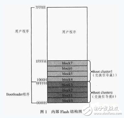
In order to prevent the Bootloader's own upgrade failure, the boot exchange function was designed. This function defines 2 clusters, Boot Cluster0 and Boot cluster1. Boot clustee0 is a 4 KB storage space of block0 to block3, and Boot cluster1 is a 4 KB storage space of block4 to block7. Therefore, in the actual application process, the beginning of the application program is generally defined as 2000H, that is, starting from block 8.
The flash address is 0000H to FFFFH. 7FFFFH ~ FFFFH storage space for the reserved area and special function register area, the user can not be programmed.
2 Self programming2.1 Self programming environment
2.1.1 Hardware Environment
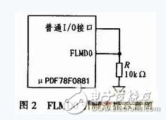
The FLMDO pin is set by the 78KO/Fx2 family of microcontrollers for Flash programming mode and is used to control the MCU to enter programming mode. Under normal operating conditions, the FLMDO pin is pulled down to ground. To enter self programming mode, the FLMDO pin must be set high. Therefore, the level of the FLMD0 pin is controlled through a normal I/O interface. as shown in picture 2.
2.1.2 Software Environment
1) Use the general-purpose register bank3, self-programming library function, need to call the general-purpose register bank3. Therefore, general register bank3 cannot be operated during self programming.
2) Using 100 B RAM (entry RAM) as a work area for functions in the hidden ROM, the entry RAM is the RAM area used by the Flash memory self programming sample library. The user program needs to keep the block area. When calling the library, you need to specify the start address of this area. The entry RAM address can be specified between FB00h and FE20h.
3) 4 to 256 B RAM is used as a data buffer and must be an internal high speed RAM area other than FE20H to FE83H.
4) Maximum 39 B RAM as a stack of hidden ROM functions.
5) Functions in the hidden ROM are called by applications in 0000H to 7FFFH.
2.2 Self programming process
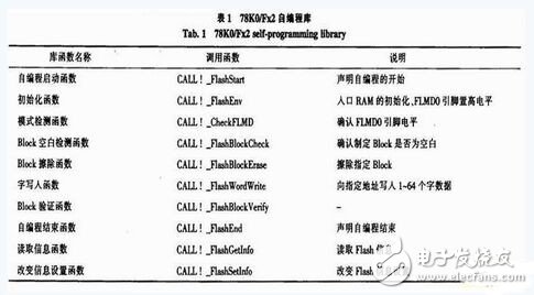
The self-programming function uses a self-programming software library to complete the user program's reprogramming of the Flash content. If an interrupt occurs during the self-programming process, the self-programming will pause to respond to the interrupt. After the interruption ends, the self-programming process will continue after the self-programming mode is restored. The 78K0/Fx2 self-programming software library is written in assembly language, as shown in Table 1.
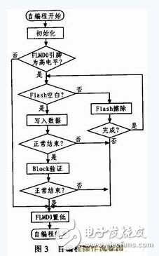
The self-programming operation flow is shown in Figure 3. When the MCU receives the self-programming execution signal, it begins to enter the self-programming mode. Set the FLMDO pin high, initialize the entry RAM, and open up space for self-programming library functions. When it is confirmed that FLMD0 is in the self-programming state, it starts checking whether the area to be programmed is a blank area. When the programmed area is not a blank area, it is first erased and then programmed in this area. Verify after programming. If the check is correct, set the FLMDO pin low to exit the self programming mode.
Product program upgrades include application upgrades and bootloaders (Bootloader itself) upgrades. In order to prevent the boot program from making mistakes in the process of upgrading, which causes the MCU to fail to start, the boot exchange function is designed. The implementation of boot exchange is illustrated in FIG.
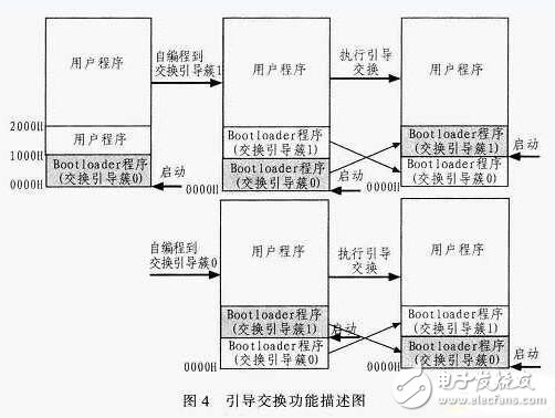
1) The old Boot program first programs the new Boot program to Boot Cluster 1, then sets the boot swap flag and forces the watchdog to reset.
2) After the reset is started, the MCU sees the swap flag and starts booting from the swap boot cluster 1. The new Boot program at switch boot cluster 1 will check the swap flag bit. If the swap flag is set, the new Boot program will erase the Boot Cluster 0 area and copy itself to the swap boot O, then clear the swap flag to force the watchdog to reset. .
3) After the reset starts, the MCU sees the swap flag cleared. From the start of the swap boot cluster 0 again. This completes the upgrade of the boot program itself. Even if an abnormal situation such as a power failure occurs during the upgrade, the Boot program upgrade can be completed again after the power is turned on again. This prevents the upgrade from failing due to an abnormal situation such as a power failure during the upgrade, and the MCU cannot be started. This makes Boot program upgrades safe and reliable.
4 Bootloader Design4.1 Simple Bootloader
A simple bootload includes 5 elements.
1) Bootloader Boot Loader The Bootloader program is a small program executed before executing the application program. After the Bootloader program transfers control to the application program, the Bootloader program will not be executed until the MCU is reset. Therefore, it is necessary to generate a signal to trigger the MCU to start the Bootloader program. The signal can be an interrupt, an instruction transmitted through the serial port, or a signal triggered by another program.
2) Execute Bootloader Signals When the microcontroller program starts, whether the MCU loads a new application program or executes an already existing program depends on the external signal. The signal can be a port signal at power-on, used to control whether the MCU loads a new program or an old program, or it can be an instruction received from a serial port.
3) Transfer the new code to the MCU Transfer the new application data via RS485, I2C, CAN or USB. Because the code to be transmitted generally exceeds the MCU's RAM capacity, some control over data traffic is required. The XON/XOFF software handshake protocol is generally used. The format of the transfer code is generally Intel hex format.
4) Automatic programming of new Flash code Each time the MCU receives a new batch of data, it will be programmed to the correct Flash address. If this address is not blank, the MCU must be erased before programming. It is usually necessary to check the contents of the memory after programming or programming.
5) Transfer control to a valid application After receiving and programming new code, the Bootloader writes a checksum or other unique byte sequence to a fixed memory location. The bootloader checks this value. If this value exists, the bootloader passes control to the application.
4.2 Intelhex format
The online upgrade program code uses the Intel hex format file output by the compiler. Intel hex files are often used to save the program code of a microcontroller or other microprocessor. It saves the object code image in the physical program store. The general programmer supports this format. The numbers in the Intel hex file record are in hexadecimal format. In the InteI hex file, each row contains a HEX record. Intel hex files are usually used to transfer programs and data that will be stored in Flash or EEPROM. Intel hex consists of any number of hexadecimal records. Each record contains five fields, which are arranged in the format shown in Figure 5.

Each section consists of at least 2 hexadecimal encoded characters. They make up 1 byte. The meaning of each section is as follows:
1) Each Intel hex record begins with a colon, which is used to determine the start of an Intel hex record during the self-programming process.
2) The data length represents the number of data bytes in the current record.
3) The address represents the starting address of the data in the current record in the storage area.
4) There are four types of HEX record types: 00-data record; 01-file end record; 02-extended segment address record; 03-transfer address record. NEC compiler output in Intel hex file. Only contains data types 00 and 01. O1 is used as a decision flag for the end of data in the self programming process.
5) The data domain is used to store the content that needs to be written to Flash. A record can have many data bytes. The number of data bytes in the record must match the value in the data length.
6) The checksum is the 2's complement of the sum of all bytes in the record from the data length to the last byte of the data field.
According to the above description, the received Inter hex file must be decoded in the program to obtain the data and data address, and the received data is verified, and then the correct data received is programmed to the corresponding address of Flash.
4.3 Bootloader Design Ideas
After the microcontroller receives the start signal, restart the program. At startup, the Boot code is executed first. The Boot code checks whether an upgrade signal is received. If it is necessary to upgrade the program, the new application program is received through the serial port or other communication interface. The loader program writes a new application program code into the microcontroller flash. Finally check the check digit to check if the program is valid. If valid, the Bootloader gives the CPU MCU control to the application. The entire upgrade process is complete. The Bootloader execution process is shown in Figure 6.
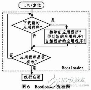
It should be noted that the Bootloader's own updates and application updates need to be handled differently. The bootloader update or the application update is determined by recognizing the programmed address of the received data. If the programming address starts from 0000H, the bootloader is updated. Bootloader update needs to perform the boot swap function; if it is an application update, the CPU will be handed over to the application directly after the end of self programming.
5 Concluding remarksThis article discusses the self-programming function of the 78KO/FC2 series μPD78F0881 microcontroller and the Bootloader design method. Described specifically through the microcontroller serial port to upgrade the corresponding application through the Bootloader. This version of the Bootloader uses a crystal oscillator 20 MHz, set the baud rate to 115 200 through the serial port Uart60, and successfully upgrades and updates user applications on the μPD78F0881 microcontroller. In the following work, the design of the Bootloader should face more communication interfaces. For example, upgrading via CAN bus interface, upgrading via USB interface, and so on. The development and wide application of Bootloader technology will surely become an important part of the development of embedded products. It will bring great convenience to the application and development of networked products, especially to the later maintenance and upgrade.
USB4 specifies tunneling of:
USB 3.2 ("Enhanced Superspeed") Tunneling
DisplayPort 1.4a -based Tunneling
PCI Express (PCIe)-based Tunneling
Main Benefits of USB 4
The new USB 4 standard has three main benefits over prior versions of USB.
40 Gbps Maximum Speed: By using two-lane cables, devices are able to operate at up to 40 Gbps, the same speed as Thunderbolt 3. The data is transmitted in two sets of four bidirectional lanes.
DisplayPort Alt Mode 2.0: USB 4 supports DisplayPort 2.0 over its alternative mode. DisplayPort 2.0 can support 8K resolution at 60 Hz with HDR10 color. DisplayPort 2.0 can use up to 80 Gbps, which is double the amount available to USB data, because it sends all the data in one direction (to the monitor) and can thus use all eight data lanes at once.
Better Resource Allocation for Video, PCIe: In lieu of alternative mode where the other interface takes over the connection, USB 4 devices can use a process called "protocol tunneling" that sends DisplayPort, PCIe and USB packets at the same time while allocating bandwidth accordingly.
Usb4 Cable,Usb To Usb4,Usb 4 Cable,Usb 4 Wires
UCOAX , https://www.ucoax.com