1 Introduction
High-intensity discharge lamps, such as mercury lamps, high-pressure sodium lamps and metal halide lamps, have found wide application in outdoor lighting. These lamps are powerful and heat-generating, and the ballasts and triggers used are usually mounted separately from the lamp. However, for low power, low heat generation, strong brightness, and the need for ballasts, triggers and lamps as close as possible to the installation, the current high-power high-intensity discharge lamps and their ballasts are difficult to meet. This requirement.
This paper introduces a design scheme of an electronic ballast for low-power (about 35W) metal halide lamps, which uses active power factor correction technology to make the power factor close to 1. This greatly reduces the same line power factor in the ballast. Related losses. The electronic ballast operates at a frequency of about 44 kHz, and uses a small, low-consumption transformer to form a unique starting circuit that can generate a pulse voltage of 6000 V, which is sufficient to illuminate the metal halide lamp. Because the whole ballast has a simple circuit and high work efficiency, it can be installed compactly and integrated with the metal halide lamp.
2 system design block diagram
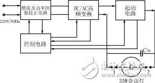
Figure 1 is a schematic block diagram of the electronic ballast. The 220V/50Hz AC power from the power grid is rectified and power factor corrected, and becomes a DC voltage of about 300V. The DC/AC high-frequency converter generates a high-frequency voltage output of about 44kHz, and the DC voltage is also supplied to the starting circuit. A starting pulse voltage of approximately 6000V is provided for the metal halide lamp and ballast impedance. The 44 kHz high frequency voltage output from the DC/AC conversion circuit is connected to the pin 1 of the metal halide lamp, and the high voltage pulse output from the starting circuit is connected to the pin 2 of the lamp. The filter capacitor C30 is also connected to the lamp pin. The control circuit provides a switch control signal, a temperature monitoring signal, and an abnormal state protection signal for the above circuit.

Figure 1: Block diagram of an electronic ballast
HP chromebook 11 g8 ee,chromebook 11 3120,hp 11.6 chromebook,hp chromebook 11 g8
S-yuan Electronic Technology Limited , https://www.laptoppalmrest.com