The use of a three-phase asynchronous motor for a long time is often caused by the ambiguity or loss of the label on the lead wire of the stator three-phase winding, which causes the head and tail marks of the stator three-phase winding lead line to be chaotic. Therefore, a serious accident of motor damage is often caused by the reverse connection of the stator windings. Therefore, it is very important to accurately and accurately identify the head and tail ends of the motor stator three-phase winding lead-out line.
The common methods for discriminating the motor stator winding lead and tail are as follows:
1. Residual magnetic method1) First find three windings
Using a DC mA meter (or mA, uA block of the multimeter), first test the six lead wires of the 3-phase winding of the motor under test. The two lead-out heads of the path are divided into three groups and are divided into three groups.
2) Determine the head and tail by the residual magnetization method
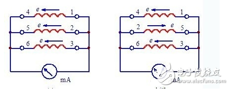
Connect the mA meter to the two lead wires of any two groups in the 3 groups. The other four lead wires can be connected in series as shown in Figure 1 a. At this time, the motor rotor is slowly rotated by hand. If the milliampere meter indicates that the motor is not moving or the amplitude of the swing is small, the connection is correct (ie, the corner joint and the tail are normal), as shown in a of FIG. 1; First, swap the two lead ends of a group that are not connected to the mA meter and try again, as shown in Figure 1b. If the pointer does not move, the instructions are correct and the end is correct. If the pointer is still oscillating, it means that the two sets of lead-out heads connected to the mA meter are head or tail, as shown in c and d of Fig. 1. At this time, the head and tail positions of the lead wires of one of the two groups connected to the mA meter can be changed and then tried again until accurate.

Figure 1 Determine the head and tail of the winding by the residual magnetization method
In this method, when the rotor rotates, the residual magnetism in the rotor induces an electromotive force in the three-phase winding of the stator, so that the milliampere meter can distinguish the head and the tail of the lead wire. However, the magnitude of this induced electromotive force is related to the magnitude of the remanence of the rotor, the number of coil turns, and the speed of the rotor. Therefore, you must pay attention to the measurement:
1) The rotor of the motor must have residual magnetism, that is, the motor must be operated;
2); The speed of rotation of the rotor should be uniform and not too different.
Another method of detecting residual magnetism:
Rotate the rotor, if the pointer is not moving, no current indication (see Figure a below), indicating that the winding head and tail connection method is correct. That is, the three heads of the three-phase windings of 1, 2, and 3 are connected together (the tails of the four-phase windings of 4, 5, and 6 are also connected correctly); if there is a current indication in the ammeter (see Figure b below), the connection error is indicated. , after the adjustment, try again.

Figure 2 Remanence and current meter method
The principle is that when the connection is correct, the current vector sum of the three-phase winding is zero, and there is no current indication; when the head and tail are connected incorrectly, the current is not zero, and there is a current indication.
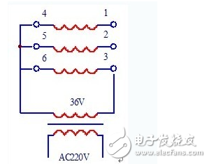
2, AC induction methodThere is a 36V safe running light transformer that rubs the door lead of the three-phase winding of the motor stator, and the two lead wires with sparks after rubbing are grouped into three groups.
Then connect the three wire ends of 4, 5, 6 (see Figure 2) of the three groups together, connect to one end of the transformer output power line, and take the other wire head of the three groups (such as 3), and connect to the transformer. Output the other end of the power cord. The remaining two wire ends 1, 2 phase to the rub, if there is no spark, then the 1 and 2 ends are the beginning (or the end); then change the wire 2, connected to the transformer power output line, put 1, 3 Rubbing each other, if there is no spark, it means that the thread head 3 is the same as 1, 2, but also the beginning (or the end). If sparks are generated during the rubbing, any one of 4, 5, and 6 should be replaced by the start and end of a winding, and then the rubbing should be thought of until there is no spark, then the two names of the same name can be identified.

Figure 3 (external supply of AC power) AC induction method
This method can also be performed with an AC voltmeter. Connect the 3 and 6 wires to the output power line of the transformer, and measure the voltage U32 and U31 between the 3 and 2 wire heads and the 3 and 1 wire heads with the AC voltage. If U32≈U31》 U36, the wire ends 1, 2, 3 (or line heads 4, 5, 6) are the beginning or the end; if U32 ≈ U31 "U36, it means that the 3, 6 two-wire head is reversed, and the 3 and 6-wire heads can be reversed; in phase, if U32" U36, and U31 "U36, it means that the 1, 4 two-wire head is reversed, and the two-wire heads can be exchanged.
The above detection principle is to use the same name end of the two windings to connect in series, the induced voltage is connected to cancel, the different names are connected in series, and the principle of the induced voltage is added to detect. That is, the AC voltage is supplied to one of the phase windings, and the addition and subtraction of the induced voltage of the three windings are measured.
We have been in the Lithium Battery industry for many years and always adhere to the full capacity of the product.Sufficient quantity is not false standard,ensure the power stability of lithium battery ,stable endurance. Our 3.2v 50ah LiFePo4 Battery battery have high diacharge, low battery resistance, stable discharge, longer life cycle. We have higher temperature resistance, higher power discharge.
3.2V Battery Cells,Prismatic Phosphate Lithium Batteries,3.2V 50Ah,3.2v lifepo4 battery,3.2V LifePO4 Lithium Battery Pack
Jiangsu Zhitai New Energy Technology Co.,Ltd , https://www.zt-tek.com