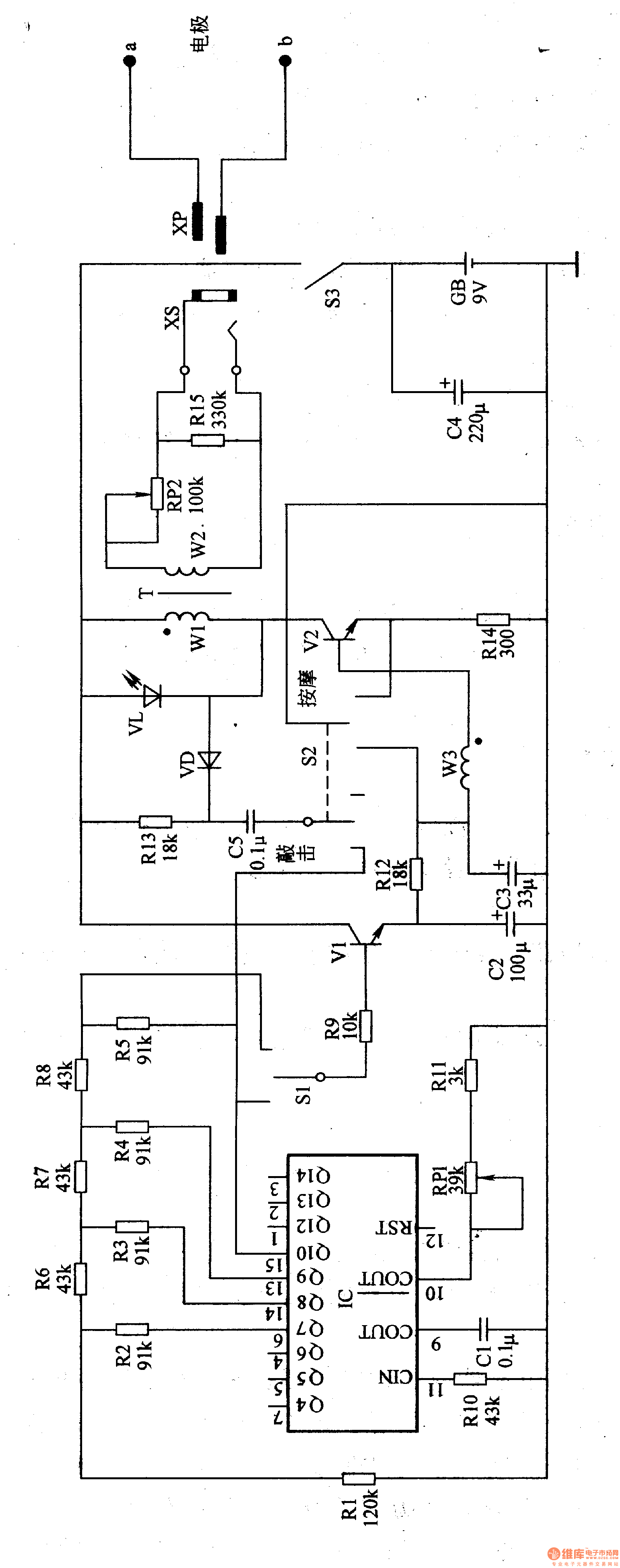
Circuit Operation Principle The electric pulse therapy device circuit consists of an oscillating frequency divider, a triangular wave forming circuit, a pulse selecting amplifier, and a boosting circuit, as shown in Figure 9-12.

The oscillating frequency divider circuit is composed of a timing divider integrated circuit IC with a built-in oscillator, a capacitor C1, a resistor R10, a R11, a potentiometer RP1, and the like.
The triangular wave forming circuit is composed of an IC and resistors Rl-R8.
The pulse selection amplifier is composed of a selection switch S1, a resistor R9, an R12, a capacitor C2, a transistor V1, and a working mode selection switch S2.
The boosting circuit is composed of an output amplifying tube V2, a step-up transformer T, a potentiometer R, and the like.
VL is the operating status indicator LED. C4 is an energy storage filter capacitor. The resistor Rl3, the diode VD, and the capacitor C5 constitute a trigger circuit.
After the power switch 53 is turned on, the oscillator inside the oscillating frequency divider oscillates, and the generated oscillating signal is outputted from the 15th pin of the IC to the square wave signal divided by 10 times. The square wave signals of the 6th, 8th, 9th, and 15th output of the IC, which are divided by 7th, 8th, 9th, and 10th, are processed into a simple triangular wave by a resistor network composed of resistors Rl-R8. The triangular wave signal and the square wave signal output from the 15-pin of the IC serve as control waveforms for two different massage methods (the square wave is used to generate a vibration massage method with constant intensity, and the triangular wave is used to generate a massage technique with a small to large intensity) After the massage method selects the switch S1 and the V1 is amplified, it is output from the emitter of the V1 to the subsequent circuit.
The working mode selection switch S2 is used to select two working modes of tapping and massage. When the SS2 is placed in the tap position, the square wave signal outputted by the IC pin 15 directly controls the operating frequency of the booster circuit (high voltage generator); when the 52 is placed in the massage position, the operating frequency of the booster circuit is controlled by the resistor. The output signals of the LRC2, W3 (one winding of T), the capacitor C3, and the output signal of the V1 emitter are determined together.
After the booster circuit is operated, a low-frequency pulse high voltage is generated from the secondary winding (winding W2) of T, and the voltage is controlled by the R-tooth, and is applied to the lesion part of the human body through the two external electrodes a and b (the heart part and the head) Partially disabled) to complete the massage or tapping (beating) action.
When the therapeutic device is in operation, the light-emitting diode VL emits light.
Adjusting the resistance of RPl can change the operating frequency of the oscillating crossover, thus changing the rhythm of the massage action.
By adjusting the resistance of RP2, you can change the amplitude of the pulse voltage to change the intensity of the massage or tap.
Component selection
Rl-R5 uses 1/4W or 1/8W carbon film resistors.
RPl selects a small synthetic membrane potentiometer; R-Tu selects a small synthetic membrane potentiometer with switch (integrated with S3).
Cl and C5 use monolithic capacitors or polyester capacitors; C2-C4 selects aluminum electrolytic capacitors with a withstand voltage of l6V.
VD selects 1N4007 silicon rectifier diode for use.
VL selects φ5mm LED.
Vl selects S9014 type silicon NPN transistor for use; V2 selects 3DA4O1A or 2SD401, 2N5655, MJE5655 type NPN transistor.
IC selects CD4060 type timing divider integrated circuit.
S1 uses a small toggle switch; S2 uses a bipolar two-position switch.
XS and XP use φ3.5mm headphone jack and plug.
T is made using a magnetic can of φ3Omm and a high-strength enameled wire of φO.14mm. The Wl winding is wound around 16 turns, W2 is wound around 900 turns, and the W3 winding is wound around 10 turns.
The electrodes a, b use finished conductive rubber electrodes.
5 Inch Full Range,5 Inch Full Range Speaker,Neodymium Loudspeaker,5 Inch Loudspeaker
Guangzhou BMY Electronic Limited company , https://www.bmy-speakers.com