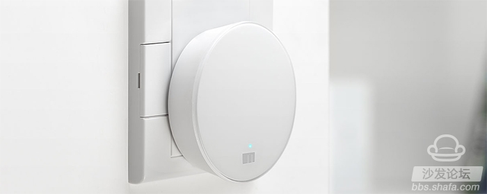
As its model shows, the Meizu router mini's biggest feature is the mini, which uses a simple circular design, a diameter of 67mm, a thickness of 23mm, a net weight of 71.8g, it can be said that the size of only the palm size, using a built-in 5V 1.0A power supply design It can be used by plugging it directly into a socket, without having to drag a small tail like other external power routers. For the sake of volume compromise, the Meizu router mini provides only a 100Mbps adaptive LAN/WAN interface. The WPS and reset are also integrated on a single button, with a blue LED as the status indicator.

The Meizu router mini is built with the MediaTek MT7628AN chip solution. It is equipped with 64MB of memory and 16MB of flash memory, and has 3 FPC flexible circuit board antennas. The MT7628AN integrates a 580MHz single-core MIPS 24KEc processor and 2x2 MIMO 2.4GHz-band 802.11n wireless network controller, commonly found on entry-level router platforms. Therefore, the ordinary version of Meizu router mini can only provide 2.4GHz band wireless network, the theoretical maximum bandwidth of 300Mbps.
Meizu router mini Pro is equipped with MediaTek MT7610E chip on the basis of the regular version. This is a 5GHz band radio network controller that supports the 802.11ac standard and provides a 5GHz band wireless network with a theoretical maximum bandwidth of 433Mbps. Therefore, the Meizu router Mini Pro is an AC750 grade product.

In terms of system firmware, Meizu Router mini adopts the “Wizards†router management system based on OpenWRT customization, which can realize adaptive network connection, one-click adjustment of network speed, flood protection network, unlimited time switch and support the use of mobile phones for remote control. Use is still relatively simple.
Usually,10 & 20 layers PCB are HDI board,but some are not .Some with big trace width and space,holes are over 0.3mm too. We have much experience in doing 10 Layer PCB & 20 layer PCB.
A ten-layer board should be used when six routing layers are required. Ten-layer boards, therefore, usually have six signal layers and four planes. Having more than six signal layers on a ten-layer board is not recommended. Ten-layers is also the largest number of layers that can usually be conveniently fabricated in a 0.062" thick board. Occasionally you will see a twelve-layer board fabricated as a 0.062" thick board, but the number of fabricators capable of producing it are limited..
High layer count boards (ten +) require thin dielectrics (typically 0.006" or less on a 0.062" thick board) and therefore they automatically have tight coupling between layers. When properly stacked and routed they can meet all of our objectives and will have excellent EMC performance and signal integrity.
A very common and nearly ideal stack-up for a ten-layer board is shown in Figure 12. The reason that this stack-up has such good performance is the tight coupling of the signal and return planes, the shielding of the high-speed signal layers, the existence of multiple ground planes, as well as a tightly coupled power/ground plane pair in the center of the board. High-speed signals normally would be routed on the signal layers buried between planes (layers 3-4 and 7-8 in this case).
10 Layer PCB
10 layer PCB 10 layer TG170 PCB 10 layer design
Storm Circuit Technology Ltd , https://www.stormpcb.com