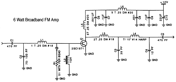
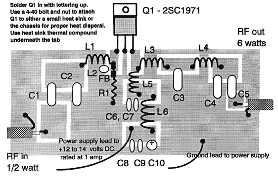
6 Watt Frequency Modulation (FM) Broadcast Amplifier

Component list
| Quantity | Component parameters and description | Numbering |
| 2 | 470 pF mica capacitor | C1, C5 |
| 1 | 75 pF mica capacitor | C2 |
| 1 | 39 pF mica capacitor, or 25-80p mica trimmer capacitor | C3 |
| 1 | 12 pF mica capacitor, or 10-50p mica trimmer capacitor | C4 |
| 2 | 0.001 uF porcelain dielectric capacitor (marked 102, .001, or 1n) | C6, C8 |
| 2 | 0.1 uF ceramic dielectric capacitor (marked 104, .1, or 100n) | C7, C9 |
| 1 | 22 uF electrolytic capacitor (note the positive and negative levels) | C10 |
| 1 | A hollow coil with a diameter of 1.2mm copper wire and a diameter of 6.5mm 1 turn | L1 |
| 1 | 1 uH choke inductor (RF choke) | L2 |
| 1 | A hollow coil wound with a 1.2mm diameter copper wire is 6.5mm in diameter and 2 turns elongated to 4mm | L3 |
| 1 | A hollow coil wound with a 1.2mm diameter copper wire is 6.5mm in diameter and 3 turns elongated to 6mm | L4 |
| 2 | A hollow coil wound with a copper wire with a diameter of 0.8mm has a diameter of 6.5mm and 5 turns elongated to 8mm | L5, L6 |
| 1 | 56 ohm resistor put a magnetic bead on the base end of Q1 | R1 |
| 1 | 2SC1971 RF transistor | Q1 |


Follow WeChat
Interesting and informative information and technical dry goods

Download Audiophile APP
Create your own personal electronic circle

Follow the audiophile class
Lock the latest course activities and technical live broadcast
comment
Publish
related suggestion
[Photo] 40 Watt Frequency Modulation (FM) Broadcast Amplifier ![[Photo] 40 Watt Frequency Modulation (FM) Broadcast Amplifier](http://i.bosscdn.com/blog/20/06/41/520516528.gif)
Indicators and characteristics of the circuit: component list
Published on 2006-04-15 20:51 • 272 views
![[Photo] 40 Watt Frequency Modulation (FM) Broadcast Amplifier](http://i.bosscdn.com/blog/20/06/41/520516528.gif)