PID controller (proportion integration-differentiation controller) consists of a proportional unit P, an integral unit I, and a differentiation unit D. Through the Kp, Ki and Kd three parameter settings. The PID controller is mainly suitable for systems whose basic linear and dynamic characteristics do not change over time. This article first introduced the working principle of the PID controller, followed by the pid controller input and output, and finally introduced the PID controller parameter tuning and PID controller control implementation, follow the specific small series together to find out.
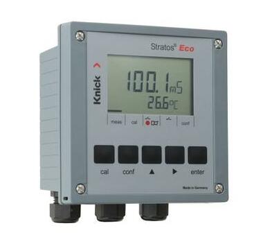
PID controllers are widely used in industrial process control. Approximately 95% of closed-loop operations in the industrial automation sector use PID controllers. The controller is combined in such a way that a control signal is generated. As a feedback controller, it provides control output to the required level. Prior to the invention of the microprocessor, analog electronics implemented PID control. But today all PID controllers are handled by the microprocessor. The programmable logic controller also has built-in PID controller instructions.
By using a low-cost, simple switch controller, only two control states are possible, such as full-on or full-close. It is used for limited control applications and these two control states are sufficient to control the target. However, the oscillation characteristics of this control limit its use and are therefore being replaced by PID controllers.
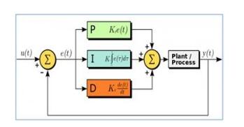
The PID controller maintains the output so that there is a zero error between the process variable and the setpoint/desired output through closed-loop operation. The PID uses three basic control actions, which will be explained below.
P-controller:
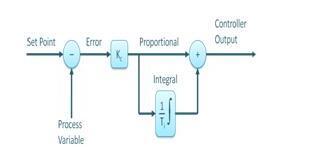
The proportional or P-controller gives an output proportional to the current error e(t). It compares the expected or setpoint value with the actual value or feedback process value. The resulting error is multiplied by the proportional constant to get the output. If the error value is zero, the controller outputs zero.
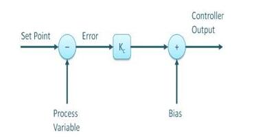
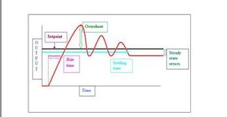
This controller requires an offset or manual reset when used alone. This is because it has never reached a stable state. It provides stable operation but always maintains a steady state error. As the proportional constant Kc increases, the response speed increases.
I-controller
Since the p-controller always has a deviation between the process variable and the setpoint, an I-controller is needed, which provides the necessary action to eliminate the steady-state error. It integrates a period of error until the error value reaches zero. It maintains the value of zero for the final control device.
When a negative error occurs, the integral control reduces its output. It limits the response speed and affects the stability of the system. The speed of the response is increased by reducing the integral gain Ki.
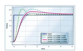
In the above figure, the steady-state error gradually decreases as the gain of the I controller decreases. For most situations, the PI controller is especially suitable for applications where high speed response is not required.
When using a PI controller, the I-controller output is limited to a certain extent, overcoming the integral saturation, where the integral output goes up even when the zero error state increases, due to the non-linear condition in the plant.
D-controller
I-controllers do not have the ability to predict wrong future behavior. So once the set value changes, it will react normally. The D controller overcomes this problem by predicting the wrong behavior in the future. Its output depends on the rate of change of error with respect to time, multiplied by the differential constant. It provides startup for the output, thereby increasing system response.
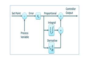
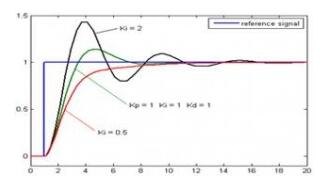
In the figure above, the D controller has more responses than the PI controller and the output setup time is reduced. It improves the stability of the system by compensating the phase delay caused by the I controller. Increasing the differential gain will increase the response speed.
enter:
The measured (controlled) value of the controlled object - PV, also known as the process value; generally from the measurement unit.
The set value of the controlled object - SP or SV, also called the set value; generally from the operating unit.
Output:
The output value of the PID controller - CO or CV or MV, also known as PID output value; generally output to the Communicator or output card.
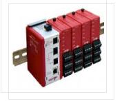
The parameter setting of the PID controller is the core content of the control system design. It is based on the characteristics of the controlled process to determine the size of the PID controller's proportional coefficient, integration time and derivative time. There are many ways to set PID controller parameters. To sum up, there are two major categories: First, the theoretical calculation method. It is mainly based on the system's mathematical model, through the theoretical calculation to determine the controller parameters. The calculation data obtained by this method may not be directly used, but must also be adjusted and modified through actual engineering. The second is the method of engineering setting. It mainly relies on engineering experience and is directly conducted in the test of the control system. The method is simple and easy to master. It is widely used in engineering practice. The engineering tuning methods for PID controller parameters include critical ratio method, response curve method and attenuation method. Each of the three methods has its own characteristics. Its common point is to pass the test, and then adjust the controller parameters according to the engineering experience formula. However, no matter which method is adopted, the controller parameters need to be adjusted and improved in the actual operation. The critical ratio method is now generally used. The steps for setting the parameters of the PID controller using this method are as follows: (1) First, a short enough sampling period is pre-selected for the system to work; (2) Only the proportional control is added until the system has a critical oscillation of the step response to the input. Make a note of the proportional amplification factor and the critical oscillation period at this time. (3) Calculate the parameters of the PID controller using the formula under a certain degree of control.
In actual debugging, you can only set an empirical value first, and then modify it according to the adjustment effect.
For temperature systems: P([%]) 20--60, I(min) 3--10, D(min) 0.5--3
For the flow system: P([%]) 40--100, I(min) 0.1--1
For the pressure system: P([%]) 30--70, I(min) 0.4--3
For liquid level systems: P([%])20--80, I(min) 1--5
Parameter tuning to find the best, from small to large order check
First, after the proportion of points, and then add the differential
The curve is oscillating very frequently and the proportional dial must be enlarged
The curve floats around the Grand Bay, and the proportional dial moves towards the small pull
The curve drifts back slowly and the integration time goes down
Long period of curve fluctuations, longer integration time
The curve oscillates at a high frequency, first reducing the differential
Slow fluctuations due to large fluctuations. Differential time should be longer
Two curves for the ideal curve, 4 to 1 before high
A look at the second tone and more analysis, the adjustment quality will not be low
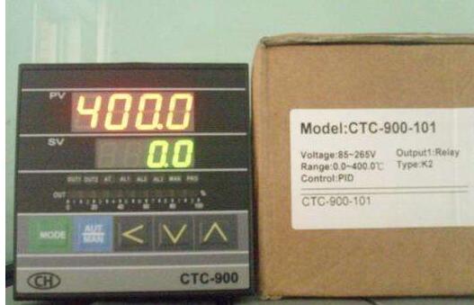
1, PID feedback logic
The feedback logic of various inverters is different from each other, and they even have similar titles and opposite meanings. The design of the system shall be based on the instructions of the inverter selected. The so-called feedback logic refers to the control polarity of the output frequency of the inverter by the feedback signal detected by the controlled physical quantity via the sensor. For example, in a central air-conditioning system, the output frequency of the inverter and the speed of the water pump motor are adjusted by controlling the return water temperature. In winter heating, if the return water temperature is low, the feedback signal decreases, indicating that the room temperature is low, requiring the inverter output frequency and motor speed to increase the flow of hot water; and in the summer cooling, if the return water temperature is low The feedback signal decreases, indicating that the room temperature is too low, which can reduce the frequency converter output frequency and motor speed. Reduce the flow of cold water. From the above, it can be seen that the same temperature is lower, the feedback signal is reduced, but the frequency change direction of the inverter is reversed. This is the reason for introducing feedback logic. The function selection of several kinds of frequency converter feedback logic is shown in Table 1.
2, open PID function
To implement the closed-loop PID control function, the PID function should be preset as valid first. There are two specific methods: First, preset through the function parameter code of the inverter. For example, if Conv CVF-G2 series inverter is used, when parameter H-48 is set to 0, there is no PID function; when it is set to 1, it is common. PID control; when set to 2, constant pressure water supply PID. The second is determined by the state of the external multi-function terminals of the inverter. For example, Yaskawa CIMR-G 7A series inverter, as shown in Fig. 1, is one of the multi-function input terminals S1-S10, and is preset by function codes H1-01 to H1-10 (corresponding to terminals S1-S10). For 19, the terminal has the function of determining whether the PI[) control is valid. This terminal is invalid when the common terminal SC is "ON", and it is valid when "OFF". It should be noted that. Most frequency converters have both of the above preset methods, but there are only a few brands of inverters.
In some systems with less stringent control requirements, sometimes the use of only the PI control function, do not start the D function to meet the needs, such a system debugging process is relatively simple.
3, target signal and feedback signal
To make certain physical quantity in the frequency conversion system stable at the expected target value, the PID function circuit of the frequency converter constantly compares the feedback signal with the target signal, and adjusts the output frequency and the motor speed in real time according to the comparison result. Therefore, the inverter's PID control requires at least two control signals: the target signal and the feedback signal. The target signal mentioned here is the electrical signal corresponding to the expected stable value of a certain physical quantity, also known as the target value or the given value; and the electrical signal corresponding to the actual value measured by the physical quantity by the sensor is called a feedback signal, also called feedback quantity or The current value. The function of PID control is shown in Figure 2. There is a PID switch in the picture. The PID function can be enabled or disabled by the function parameter setting of the inverter. When the PID function is valid, the PID circuit determines the operating frequency. When the PID function is invalid, the frequency setting signal determines the operating frequency. The PID switch, action selection switch, and feedback signal changeover switch are all determined by the setting of the function parameter.
4, the target value given
How to transmit the command information of the target value (target signal) to the inverter, various inverters have chosen different methods, and in summary there are basically two kinds of schemes: First, the automatic conversion method, that is, the inverter preset PID function When it is valid, the frequency setting function of its open-loop operation is automatically converted to the target value.
Hot Melt Type Fiber Optic Fast Connector
Hot Melt Type Fiber Optic Fast Connector,Afl Fast Connect Lc,Fast Connector Fiber
Ningbo Fengwei Communication Technology Co., Ltd , https://www.fengweicommunication.com