Some programming elements in the PLC ladder use the names of relays such as input relays, output relays, internal auxiliary relays, etc., but they are not real physical relays but some memory units (soft relays), each of which is a soft relay. Corresponds to one memory location in the mirror register in PLC memory. If the memory cell is in the "1" state, it means that the coil of the corresponding soft relay in the ladder diagram is "energized", its normally open contact is closed, the normally closed contact is opened, and this state is said "1" of the soft relay. "" or "ON" state. If the memory cell is in the “0†state, the state of the coil and the contact corresponding to the soft relay is opposite to that described above, and the soft relay is said to be “0†or “OFFâ€. These "soft relays" are also often referred to as programming elements in use.
Energy flowThere is an imaginary "conceptual current" or "Powerflow" flowing from left to right, which is consistent with the order of logic operations when executing the user program. Energy flow can only flow from left to right. Using the concept of energy flow can help us to better understand and analyze ladder diagrams.
3. BusbarsThe vertical common line on both sides of the ladder is called busbar. When analyzing the logic relationship of the ladder diagram, in order to borrow the analysis method of the relay circuit diagram, it can be imagined that there is a left, right, and negative DC power supply voltage between the left and right bus bars (left bus and right bus), and the power flow between bus bars. "From left to right. The right bus may not be drawn.
4. Ladder logic solutionAccording to the state and logical relationship of each contact in the ladder diagram, the state of the programming element corresponding to each coil in the diagram is obtained, which is called the logical solution of the ladder diagram. The logical solution in the ladder diagram is from left to right and from top to bottom. The result of the solution can be used immediately by the subsequent logical solution. The logic solution is based on the value in the input shadow register, not on the status of the instantaneous external input contact.
PLC ladder programming basic rulesSince the ladder diagram is a form of program representation and is not a control circuit composed of hardware, when drawing a ladder diagram, attention should be paid to the difference from the ordinary control circuit. The following basic principles should be followed when programming the PLC:
(1) The logic contacts of external input/output relays, internal relays, timers, counters, and other soft devices can be reused multiple times, eliminating the need to use complex program structures to reduce the number of contacts used.
(2) Each line of the ladder diagram starts from the left bus and the coil is at the far right. The contact cannot be placed on the right side of the coil. In the relay contactor control circuit, the contact can be added to the right side of the coil. This is not allowed in the ladder diagram of the PLC. This is shown in Figure 1(a). It is not difficult to see from the figure that the programmer's intention is that when the contacts 0.00, 0.01, and 0.02 are all closed, the coil 10.00 is driven electrically. However, in the ladder diagram, since the contact cannot be connected with the right bus bar, the figure 1(a) is converted into the format shown in FIG. 1(b), which not only satisfies the above-mentioned functions of the program but also conforms to the programming rules of the ladder diagram.

Figure 1. Conversion of coils not connected to the right bus (or contact and right bus)
(a) Ladder diagrams that do not meet programming specifications; (b) Ladder diagrams that meet programming specifications
(3) The coil cannot be directly connected to the left bus. From Fig. 2(a), it is easy to see that the programmer's intention is to make the program run 10.00, 10.01 coils to be driven. To achieve this, it is possible to use a normally closed contact of an internal relay (such as 200.00) that is not called in a program or the normally open contact of a special relay 253.15 (normally-pass relay) to drive them, satisfying the programmer's requirements. Functional requirements, but not against the ladder programming rules, as shown in Figure 2 (b) below.
(4) The same numbered coil is used twice in the same main program and is called double coil output of the same name. The double coil output with the same name can easily cause the output to be indeterminate. When programming, the double coil output of the same name should be avoided. How to avoid the double coil output of the same name can refer to the scheme shown in FIG. 3.

Fig.2 Conversion of the coil directly connected to the left busbar
(a) Ladder diagrams that do not meet programming specifications; (b) Ladder diagrams that meet programming specifications

Figure 3 double coil output of the same name and its solution
(a) The original ladder diagram; (b) Operational effects;
Generally, double-coil output with the same name should be avoided in the ladder program, because this will cause the output to be indeterminate, as shown in Figure (a) for the same name double coil output ladder. In terms of programming syntax, this ladder diagram does not violate regulations, but in actual operation, its results sometimes differ greatly from the programmer's expectations. It is not difficult to see that (a) the programmer's intention in the figure is when the contact 0.00 in the branch 1 is closed at 0.01, or the contact 0.02 in the branch 2 is closed at 0.03, or both branches When all of the contacts are closed, the coil 10.00 can be driven. However, in actual implementation, when the contacts in the contact branch 1 are 0.00 and 0.01 are closed, and when the contacts in the branch 2 are 0.02 and 0.03 are disconnected, the coil 10.00 cannot be powered. The result is shown in (b). . This is because the PLC adopts a cyclic scan processing method. After the input is sampled, the central processor operates the ladder diagram from top to bottom. In the calculation of the first-order circuit, the coil 10.00 is driven electrically, but when the second-order circuit is calculated, the coil 10.00 is not driven because the contacts 0.02 and 0.03 are opened. At the time of I/O refresh, the output is based on the final calculation result, and the coil 10.00 at this time is in the de-energized state.
(5) Ladder program must follow the principle of sequential execution, that is, from left to right and from top to bottom. If the ladder program does not meet the principle of sequential execution, it cannot input the programming software. As shown in the ladder diagram of the bridge structure shown in Figure 4(a), it is not difficult to see that the programmer's intention is that all the contacts of the branch 1 are closed, or all the contacts of the branch 2 are closed or branched. When all the contacts of the way 3 are closed, or all the contacts of the branch 4 are closed, the coil 10.00 is driven electrically. However, such a ladder diagram cannot enter the programming software or the handheld programmer because it does not comply with the programming rules. Figure 4(a) should be converted to Figure 4(b) in order to use programming software or a handheld programmer to write to the PLC memory. .

Figure 4 Bridge Circuit Conversion
(a) Bridge circuit diagram; (b) Converted ladder diagram
(6) There are no restrictions on the number of serial and parallel contacts used in the ladder diagram, and they can be used indefinitely, as shown in Figure 5.
(7) Two or more coils with different numbers in the same program can be output in parallel, as shown in Figure 6.

Figure 5 unlimited use of contacts 
Figure 6 Multiple coils with different numbers in parallel
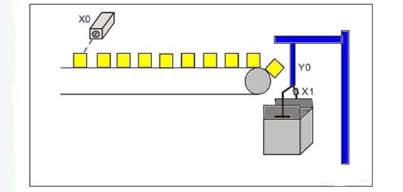
PLC counter program ladder programming exampleAfter the photoelectric sensor detects 10 products, the robotic arm will start packing. When the action is completed, the robot and counter will be reset.
Plc input required number

X0 - Photoelectric sensor for counting products. When testing the product, X0 = ON.
X1 - The robot moves to complete the sensor. After filling, X1=ON,.
PLC output required number
Y0- robot
The number of PLC counters required
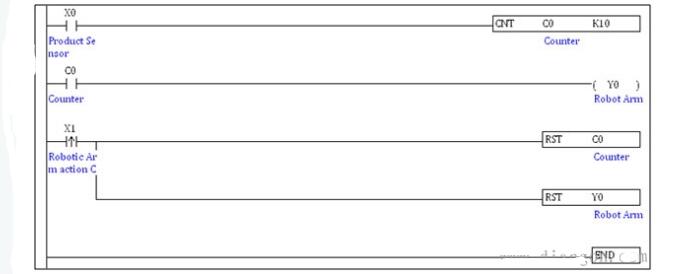
C0–Counter: 16-bit up (general)

Plc programming ladder
PLC programming ladder description:
When the photo sensor detects the product, X0 turns from off to on. C0 counts once. When C0 reaches 10, the normally open contact C0 is closed and Y0 = ON, and the robot begins to pick up the product.
When the packaging is completed, the sensor of the detection robot starts, X1 changes from off to on, and the RST instruction is executed. Y0 and C0 are reset to prepare for the next count.
So happy to know that 11th laptop is ranking the No.1 position in 2022 custom market. You can see intel core i3 11th generation laptop,Gaming Laptop i5 11th generation, laptop price i7 11th generation, etc. At this store. Maybe you will ask why 11th gen gaming laptop is so popular and welcome, mainly reason is its competitive cost and high performance. Intel i7 11th Generation Laptop cost is similar as intel i7 10th gen laptop, but performance is much better than 10th one. Besides, 12th laptop is arriving in lot at the end of 2022 at custom laptop market, price is will much competitive at that time.
Whom this Gaming Laptop is more suitable to? Of course, heavier tasks workers, no matter office jobs, education tasks, or others. However, if your clients focus more powerful cpu and performance, i7 16gb ram 4gb graphics laptop or 15 Inch Gaming Laptop with 10th cpu and 2GB graphics also alternatives.
You can contact us directly to get get right and valuable information fast. Will try our best to support every clients no matter quantity you take.
11th Laptop,Intel Core I3 11th Generation Laptop,11th Gen Gaming Laptop,Gaming Laptop I5 11th Generation,Laptop Price I7 11th Generation
Henan Shuyi Electronics Co., Ltd. , https://www.shuyioemelectronics.com