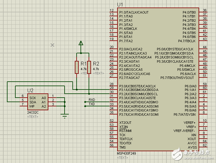
/************************************************* *****************
**
** File : I2C.c “ ​​Master Read Write |
** Version : 1.0
** DescripTIon: I2C query reads and writes 24C02
** Author : LightWu
** Date : 2013-4-26
** Must pay attention to multi-byte data read, send stop bit needs to be read before the last byte
** Otherwise, the stop bit transmission is likely to fail after the data is read, causing the slave to receive no stop bit.
************************************************** *****************/

#include
/ / Note: There must be a delay between the two sending intervals, otherwise it can not be sent again, serial transmission format:
Unsigned char PTxData[250]; // Pointer to TX data
Unsigned char PRxData[250]; // Pointer to RX data
Void UarTInit(void)
{
If (CALBC1_1MHZ==0xFF) // If calibraTIon constant erased
{
While(1); // do not load, trap CPU! !
}
DCOCTL = 0; // Select lowest DCOx and MODx setTIngs
BCSCTL1 = CALBC1_1MHZ; // Set DCO
DCOCTL = CALDCO_1MHZ;
P3SEL |= 0x30; // P3.4,5 = USCI_A0 TXD/RXD
UCA0CTL1 |= UCSSEL_2; // SMCLK
UCA0BR0 = 104; // 1MHz 9600; (104)decimal = 0x068h
UCA0BR1 = 0; // 1MHz 9600
UCA0MCTL = UCBRS0; // Modulation UCBRSx = 1
UCA0CTL1 &= ~UCSWRST; // **Initialize USCI state machine**
}
Void UartSend( unsigned char Data )
{
UCA0TXBUF = Data; // TX -》 RXed character
While (!(IFG2&UCA0TXIFG)); // USCI_A0 TX buffer ready? , send buffer empty
}
Void IICInit(void)
{
UCB0CTL1 |= UCSWRST; // Enable SW reset
UCB0CTL0 = UCMST + UCMODE_3 + UCSYNC; // I2C Master, synchronous mode
UCB0CTL1 = UCSSEL_2 + UCSWRST; // Use SMCLK, keep SW reset
UCB0BR0 = 12; // fSCL = SMCLK/12 = ~100kHz
UCB0BR1 = 0;
UCB0I2CSA = 0xA0â€â€1; // Slave Address is , note that the address needs to be shifted one bit to the right and the address of 24C02 is 0XA0, so it is necessary to write 0X50.
// 7-bit address mode, the device will send a read and write bit, exactly 8 bits.
UCB0CTL1 &= ~UCSWRST; // Clear SW reset, resume operation
}
/*******************************************
Function Name: Ucb0I2c_Start(void)
Function: I2C master mode, send write start condition
Parameters: None
Return value: None
********************************************/
Void Ucb0I2c_Start(void)
{
UCB0I2CSA = 0x50; // Slave Address is 0xd0
While (UCB0CTL1 & UCTXSTP); // Ensure stop condition got sent
UCB0CTL1 |= UCTR + UCTXSTT; // I2C TX, start condition
While(!(IFG2&UCB0TXIFG)); //waits for delivery
IFG2 &= ~UCB0TXIFG; // Clear USCI_B0 TX int flag
}
Void IICSendData( unsigned char Addr ,unsigned char Data )
{
Int i;
For(i=3000;i"0;i--); //There must be a delay between two sending intervals, otherwise it cannot be sent again
Ucb0I2c_Start();
UCB0TXBUF = Addr; // Load TX buffer
While(!(IFG2&UCB0TXIFG)); // Wait for the transfer to complete
IFG2 &= ~UCB0TXIFG; // Clear USCI_B0 TX int flag
UCB0TXBUF = Data; // Load TX buffer
While(!(IFG2&UCB0TXIFG)); // Wait for the transfer to complete
IFG2 &= ~UCB0TXIFG; // Clear USCI_B0 TX int flag
UCB0CTL1 |= UCTXSTP; // I2C stop condition
}
Void IICReadData( unsigned char Addr )
{
Int i;
For(i=3000;i"0;i--); //There must be a delay between two sending intervals, otherwise it cannot be sent again
Ucb0I2c_Start();
UCB0TXBUF = Addr; // Load TX buffer
While(!(IFG2&UCB0TXIFG)); // Wait for the transfer to complete
IFG2 &= ~UCB0TXIFG; // Clear USCI_B0 TX int flag
UCB0CTL1 &= ~UCTR ; // I2C RX, Read
UCB0CTL1 |= UCTXSTT; // I2C RX, start condition
While(!(IFG2&UCB0RXIFG)); // Wait for the reception to complete
IFG2&=~UCB0RXIFG;
PRxData[0] = UCB0RXBUF; // Read RX buffer
While(!(IFG2&UCB0RXIFG)); // Wait for the reception to complete
IFG2&=~UCB0RXIFG;
PRxData[1] = UCB0RXBUF; // Read RX buffer
While(!(IFG2&UCB0RXIFG)); // Wait for the reception to complete
IFG2&=~UCB0RXIFG;
PRxData[2] = UCB0RXBUF; // Read RX buffer
While(!(IFG2&UCB0RXIFG)); // Wait for the reception to complete
IFG2&=~UCB0RXIFG;
// must pay attention to send stop bit before the last byte read
UCB0CTL1 |= UCTXSTP; // I2C stop condition
PRxData[3] = UCB0RXBUF; // Read RX buffer
}
Int main(void)
{
WDTCTL = WDTPW + WDTHOLD; // Stop WDT
P3SEL |= 0x06; // Assign I2C pins to USCI_B0
IICInit();
UartInit();
While (1)
{
UartSend('M');
IICSendData(0X00,'A');
IICSendData(0X01,'B');
IICSendData(0X02,'C');
IICSendData(0X03,'D');
IICSendData(0X04,'E');
IICSendData(0X05,'F');
IICSendData(0X06,'H');
IICSendData(0X07,'J');
IICReadData(0x00);
UartSend(PRxData[0]);
UartSend(PRxData[1]);
UartSend(PRxData[2]);
UartSend(PRxData[3]);
}
}
Rexroth Servo Motor Replacement
Rexroth Servo Motor Replacement technical advantages:
•Optional power-off brake protection
•High positioning accuracy, stable speed, improve production efficiency
•Easy to wire and lead out, reducing engineering difficulty and cost
•Highly integrated design, reducing installation complexity and saving space
•Customizable features in a variety of sports modes
•Provide application solutions and development kit support for various scenarios, shortening the user's development cycle
•Real-time fault monitoring and protection functions, including over-current, overload, over-voltage, under-voltage, overheating, overspeed, over-tolerance protection
Rexroth Servo Motor Replacement,Rexroth Servo Motor,Rexroth Servo Drive,Rexroth Servo Motor Repair
Kassel Machinery (zhejiang) Co., Ltd. , https://www.kasselservo.com