The integrated starter alternator (ISA) technology is one of the core technologies for hybrid vehicles. The further development of this technology depends on the development of new power electronics technology. IR's Steve Clemente and Toshio Takahashi studied the future of the technology. This article describes their latest research.
This article refers to the address: http://
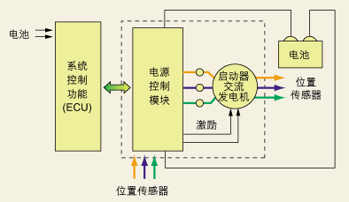
Figure 1: Basic block diagram of the starter AC engine power electrical model and its power diagram.
The automotive industry is striving to reduce the fuel consumption and exhaust emissions of conventional vehicles through electric drive retrofits and pave the way for the development of fully electric drive vehicles. The integrated starter AC engine is the basic building block for achieving these goals, and many of the cars currently used in the streets of Europe and North America have adopted this technology. Some "mild hybrid" cars use the ISA to achieve a "walk-and-go" operation that is transparent to the user on traditional engines, saving fuel consumption. "Full hybrid" cars have also begun to be marketed, with the main feature being to take on more motion operations with powerful electrical systems.
Save fuel consumption in “stop and goâ€
Perhaps the most basic function of ISA is to make the traditional car cut off the engine without idling when it encounters a red light stop. This not only reduces harmful gas emissions, but also improves fuel consumption. Of course, we can also use more advanced technology to improve the electrical performance under high peak power conditions, including electric power steering (EPS), electric turbo-assist, and internal temperature control (variable- Speed ​​climate control), electric valve control, active suspension and various X-by-Wire functions. These technologies can improve fuel consumption and performance, enhance engine control performance and efficiency, increase comfort and safety, and increase driver satisfaction while reducing overall vehicle weight.
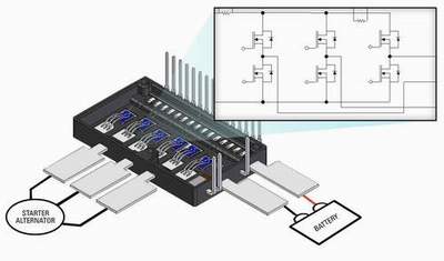
Figure 2: shows a 3-phase module with current and temperature sensing.
The main technical challenge facing the starter AC engine is to design a dynamic electrical model that provides 3 kW of power at 125 °C ambient temperature. Figure 1 shows the basic block diagram of the model and its power diagram. In a more mature implementation, the system will be divided into hardware and software: the hardware is installed on the starter AC engine, and the software is part of the main ECU. In some platforms, the load management unit is responsible for monitoring power distribution and ensuring that critical loads have the highest priority.
Figure 2 shows a 3-phase module with current and temperature sensing, which is typically mounted on the starter AC engine. Importantly, this type of basic ISA is very suitable for retrofitting existing platforms because the effort is minimal and the cost is almost negligible. This is important because it helps support the complete entry of fully electric operating technology into the market and enables cost-effective optimization even before the car introduces more advanced subsystems. Some small and medium-sized cars in Europe are ready to equip this technology because it saves fuel consumption in a “walk-and-go†operation in a car that is completely transparent to the user.
Enhanced electrical performance
In order to better play the performance of the ISA, the ISA needs to be installed in the transmission between the engine and the gearbox. Figure 3 shows how the electrical box feeds current to the motor that is integrated in an efficient space between the engine and the transfer section. This technology can provide a constant 14kW electric starting power and actively reduce the transmission system, thus completely eliminating the flywheel. This is the famous ISAD system, where D is the reduction.
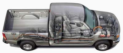
Figure 3: shows how the electrical box feeds current to the motor that is integrated in an efficient space between the engine and the transfer section.
When the red light is encountered, the gasoline engine stops running, but other accessories continue to operate under electrical drive, and the electric power is stored in a combination of a 42V lead-acid battery pack and a supercapacitor with the strongest responsiveness. Once the traffic light turns green, the driver's AC engine will start after the driver steps on the throttle, so that the car will start under battery power during engine start-up, with little or no delay or interference.
During the brief interruption of the engine, in order to ensure that the accessories are fully functional, an electrically driven hydraulic pump is required to provide a power steering wheel (the power steering wheel is expected to be replaced by a fully electrically driven EPS in the future, thereby eliminating hydraulic oil). Similarly, the traditional air conditioning system can be intelligently controlled so that the electric pump can continuously circulate hot water in winter to maintain the heat of the cab, while the electric pump continuously circulates dry and cold air in the summer.
These principles have been demonstrated in existing "mild hybrid" multi-purpose vehicles. Compared with conventional vehicles, this new type of carrier can save 10% to 15% of fuel consumption by pulling the same cargo by using regenerative braking and “stop and stop†function.
The dry battery/Ultracap capacitor network can also provide electrical power to electrical components on the board or to equipment (such as a lighter socket) that is plugged into the user's output. The top-level block diagram of the ISA is shown in Figure 4. Capacitors in parallel with the battery can improve the electrical power requirements of the newly added electrical subsystem on the board. These capacitors can play an important role in braking energy recovery.
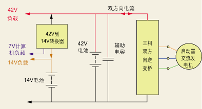
Figure 4: Capacitors in parallel with the battery improve the electrical power requirements of the newly added electrical subsystem on the board.
Designers are now beginning to benefit from high-performance sensorless architectures, which are used in architectures because of their high efficiency and controllability compared to induction motors. Although this appears to be very similar to industrial servo drives on the surface, in reality there is an essential difference between the two. The annual production of 7.5 to 12 kW industrial servo drives is about 80,000 sets, and the number of drives on a single car platform far exceeds this figure. From a technical point of view, the power modules used in these drives must withstand the strong pressures not yet known in the industry. These power modules must deliver full electrical power at 150 ° C ambient temperature with extremely high efficiency and minimal parasitics. Finally, these power modules must also minimize the transformation of existing platforms and enable products to enter the automotive market at almost negligible cost.
The module shown in Figure 5 is designed for a 42V "mild hybrid" car. The module has a half-bridge structure consisting of two large power MOSFET chips (150 mm2 each) that can exchange 600A current on a 42V bus. To reduce thermal stress, the FET is mounted on a ceramic substrate with a temperature coefficient that matches the silicon wafer. Advanced wire bonding technology ensures that the module is resistant to temperature cycling and power cycle changes that are closely related to the automotive environment. In the design, the power line must be perfectly matched to the stacked information transfer lines to minimize stray inductance below 8nH. To minimize EMI sensitivity, gate drive, sensing, and protection should also be installed on a small PCB that covers the module. The gate drive circuit can drive these FETs at 20 kHz, and the analysis of the inductive and electronic parameters can be performed on the small board.
Upgrade to full electrical operation
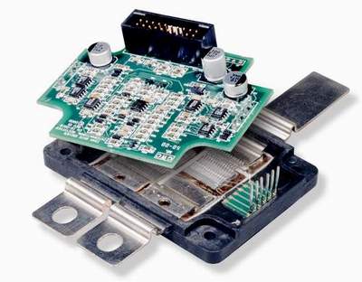
Figure 5: The module shown is designed for a 42V "mild hybrid" car.
As the power balance is transferred from the engine to the motor, the bus voltage boost is becoming more and more practical. Reducing conduction losses is no doubt more compelling than reducing costs and simplifying design simplification. In electrical device design, the conductance loss determines the size of the silicon, the package, and the heat exchanger. Since the conductance loss is proportional to the square of the current, increasing the bus voltage from 42V to 300V will reduce the conductance loss by a factor of 50, while other specifications remain the same.
It is for this reason that most of the "fully hybrid" cars that are now on the streets have bus voltages between 180V and 300V. For reference, the same module shown in Figure 5 uses a 600V IGBT architecture, and the transmitted output power can be increased by 40% to 60%.
Recently, two bus voltages are likely to coexist on the same platform. The 14V bus is still attractive because it has developed a lot of features in the 14V environment. Therefore, it is necessary to introduce a bidirectional DC-to-DC converter between the two buses for power shuttle transmission, which will also become a key part of the system architecture, because the converter is required to provide the necessary power for vehicle launch under 14V conditions. To minimize cost and increase power density, the converter can be integrated with the motor drive: sharing the same bus capacitance, bus layout and heat exchanger. Figure 6 shows a 1.5 kW converter that shares bus capacitance with the ISA. The converter uses a non-traditional topology called "ripple steering" that minimizes the specifications of the reactance device. . The converter has a conversion efficiency of 92%, a deviation of 5% or 0.7V, and a power density of 2W/cm3.
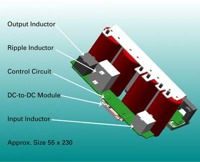
Figure 6: shows a 1.5kW converter sharing bus capacitance with the ISA.
Summary of this article
The internal combustion engine has reached the limit of performance improvement in its 100 years of development. The engine performance and efficiency that drivers now expect is difficult to achieve with any other alternative technology. However, the internal combustion engine is forced to be replaced by environmental pressure, not to mention the limited traditional fuel resources will further promote this process.
In view of the above considerations, the automotive industry is now working on alternatives, and most of them rely heavily on electrical operations. If the current automotive electronics market has an impact on general-purpose electronics and power semiconductors, the demand for future electric vehicles will help establish a new set of benchmarks, including power handling performance, operating temperature, price sensitivity and robustness. Advanced motion control and power management modules have entered the market to meet these performance needs. These alternatives will play a vital role in the design of individualized vehicles for automotive engineers in the post-total petrol era.
PC Cable:MINI DIN,D-SUB,SCSI.The display connecting line includes the data cable connecting the host computer and the display screen, and the power cable connecting the power supply.
The common data cable types are: HDMI cable, VGA cable and DVI cable. There is also a DP cable for notebook!
This product is suitable for computer and automatic connection cable with rated voltage of 500V and below. K type B low density polyethylene (LDPE) with oxidation resistance is used for insulation of cable ground wire core. Polyethylene has high insulation resistance, good voltage resistance, small dielectric coefficient and small influence of dielectric loss temperature and variable frequency. It can not only meet the requirements of transmission performance, but also ensure the service life of the cable. One
In order to reduce the mutual crosstalk and external interference between loops, the cable adopts shielding structure. According to different occasions, the shielding requirements of cables are as follows: the combined shielding of twisted pair, the total shielding of cable composed of twisted pair, and the total shielding after the combined shielding of twisted pair.
Shielding materials include round copper wire, copper strip and aluminum / plastic composite belt. Shielding pair and shielding pair have good insulation performance. If there is potential difference between shielding pair and shielding pair, the transmission quality of signal will not be affected.
PC Cable
ShenZhen Antenk Electronics Co,Ltd , https://www.antenksocket.com