What is electromagnetic compatibility
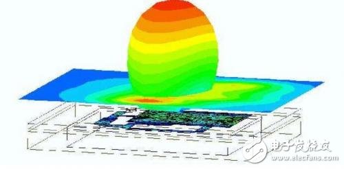
Electromagnetic Compatibility (EMC) refers to the ability of a device or system to operate in its electromagnetic environment without causing unacceptable electromagnetic interference to any device in its environment. Therefore, EMC includes two aspects: on the one hand, it means that the electromagnetic interference generated by the equipment in the normal operation of the equipment cannot exceed a certain limit; on the other hand, it means that the equipment has certain electromagnetic interference in the environment. Degree of immunity, ie, electromagnetic susceptibility.
The main research object of electromagnetic compatibility
1 Various kinds of man-made noise, such as transmission line corona noise, car noise, contactor noise itself, and noise caused by discharge when the conductor starts, electric locomotive noise, urban noise, etc.
2 The mutual influence of various public utilities (power lines, communications, railways, highways, oil and metal pipelines, etc.) in the shared corridor.
3 Reflection problems caused by large buildings such as super high-rise buildings, transmission lines, and iron towers.
4 The role of the electromagnetic environment on humans and all kinds of organisms. These include power frequency fields such as strong wires, medium and short-wave and microwave electromagnetic radiation.
5 nuclear electromagnetic pulse effects. Electromagnetic pulses from high-altitude nuclear explosions can destroy large areas of command, control, communications, computers and newspaper systems on the ground.
6 TEMPEST technology. Its substantive content is aimed at the problem of electromagnetic radiation and information leakage of information equipment, and a series of research work carried out from the aspects of information reception and protection.
7 Misoperation of electronic equipment. In order to prevent malfunctions, measures must be taken to improve the anti-jamming capability of the equipment.
8 spectrum allocation and management. The radio spectrum is a limited resource, but it is not expendable. It must be managed scientifically and fully utilized.
9 Electromagnetic Compatibility and Measurement.
10 natural influences and so on.

Measures to improve electromagnetic compatibility
1 The use of a complete shield can prevent external radiation from entering the system and can also prevent the system's interference energy from radiating outward. The shield body should maintain its integrity. The necessary doors, slots, ventilation holes, and cable holes must be properly handled. The shield body must be grounded reliably.
2 Design a reasonable grounding system. Small-signal, large-signal, and interference-prone circuits should be grounded as closely as possible. The grounding resistance should be as small as possible.
3 Using appropriate filtering techniques, the filter's passband is properly chosen to minimize leakage losses.
4 Using clipping techniques, the slice level should be higher than the working level and should be bi-directionally limited.
5 Select the correct connection cable and wiring method. If necessary, replace the long cable with fiber optic cable.
6 using balanced differential circuits, shaping circuits, integrating circuits, and gate circuits, etc.
7 system frequency allocation should be appropriate. When there are multiple main frequency signals working in a system, try to avoid the frequency of each signal, and even avoid the other party's resonant frequency.
8 The equipment in the shared corridor should be kept at a larger gauge when the conditions permit so as to reduce the mutual influence.
The basic principle of electromagnetic compatibility design
Grounding
Grounding is a very important issue for electronic devices. There are three grounding purposes:
(1) Grounding makes all unit circuits in the entire circuit system have a common reference zero potential, which ensures that the circuit system can work stably.
(2) Prevent external electromagnetic field interference. The grounding of the chassis can cause a large amount of charge accumulated on the chassis due to electrostatic induction to be discharged through the ground. Otherwise, the high voltage formed by these charges may cause spark discharge inside the device to cause interference. In addition, for the shield of the circuit, if a suitable grounding is selected, a good shielding effect can also be obtained.
(3) to ensure safe work. When a direct lightning electromagnetic induction occurs, the destruction of the electronic equipment can be avoided. When the input voltage of the commercial frequency AC power supply is directly connected to the case due to poor insulation or other reasons, the operator's electric shock accident can be avoided. In addition, many medical devices are directly connected to the patient's body and fatal dangers occur when the enclosure has a voltage of 110V or 220V.
Therefore, grounding is the main method of suppressing noise and preventing interference. Grounding can be understood as an isoelectric point or equipotential surface, which is the reference potential of the circuit or system, but not necessarily the earth potential. In order to prevent the possible damage caused by lightning strikes and the personal safety of workers, the casing of the electronic equipment and the metal components of the equipment room must be connected to the earth, and the grounding resistance should generally be small and cannot exceed the specified value.
There are basically three types of circuit grounding methods, namely single-point grounding, multi-point grounding, and mixed grounding. Single-point grounding means that only one physical point in a line is defined as a ground reference point. All other points that need to be grounded are directly connected to this point. Multi-point grounding means that each ground point in a system is directly connected to the nearest ground plane, so that the length of the grounding lead is the shortest. The ground plane can be the floor of the equipment, or the ground wire that runs through the entire system. In a relatively large system, it can also be the structural frame of the equipment.
Mixed grounding is the use of bypass capacitors and ground planes to connect only those high-frequency ground points. However, the resonance phenomenon formed by the bypass capacitor and the lead inductance should be prevented as much as possible.
2. Screen
Shielding is the isolation of metal between two spatial regions to control the induction and radiation of electric, magnetic and electromagnetic waves from one region to another. Specifically, shielded bodies are used to enclose the components, circuits, assemblies, cables, or interference sources of the entire system to prevent the electromagnetic field from diffusing outwards; and the shields are used to surround the receiving circuit, device, or system to prevent them from being exposed to the outside world. The influence of electromagnetic fields.
Because the shield body absorbs energy (eddy current loss), reflected energy (interface reflection of electromagnetic waves on the shield body), and cancellation energy (interference electromagnetic wave and internal electromagnetic wave from the outside of the wire, cable, component, circuit or system, etc.) The magnetic induction produces a back electromagnetic field on the shielding layer, which can cancel out some of the interference electromagnetic waves, so the shielding body has the function of weakening the interference.
The principle of shield material selection is:
(1) When the frequency of the interfering electromagnetic field is high, the eddy current generated in the low resistivity (high conductivity) metal material is used (P=I2R, the lower the resistivity (the higher the conductivity), the greater the consumed power) , Form a counteracting effect on foreign electromagnetic waves, so as to achieve the effect of shielding.
(2) When the frequency of interfering electromagnetic waves is low, high permeability materials should be used so that the magnetic lines of force are confined within the shield to prevent diffusion into the shielded space.
(3) In some occasions, if a good shielding effect is required for both high and low frequency electromagnetic fields, different metal materials are often used to form a multi-layer shielding body.
3. Other interference suppression methods
(1) Filtering
Filtering is an important measure to suppress and prevent interference.
The filter can significantly reduce the level of conducted interference, because the interference spectrum component is not equal to the frequency of the useful signal, and the filter has good ability to suppress these components with different frequencies of the useful signal, so that other interference suppression is difficult to play. The role. Therefore, the use of a filtering network is a powerful measure whether it is to suppress interference sources and eliminate interference coupling or to enhance the anti-jamming capabilities of receiving equipment. Decoupling a network with RC and RC can isolate the circuit from the power supply, eliminate the coupling between the circuits, and prevent interference signals from entering the circuit. For the high-frequency circuit, a CLCMÏ€-type filter composed of two capacitors and one inductor (high-frequency choke coil) can be used. There are many kinds of filters, and selecting an appropriate filter can eliminate undesired coupling.
(2) The correct choice of passive components
Practical passive components are not "ideal" and their characteristics differ from ideal ones. The practical component itself may be a source of interference, so it is very important to choose the passive component correctly. Sometimes it is also possible to use the characteristics of the components to suppress and prevent interference.
(3) Circuit Technology
Sometimes the use of shielding can still not meet the requirements of suppression and prevention of interference, and it can be combined with shielding and balanced circuit measures. Balanced circuit refers to the two wires in a two-wire circuit and all the circuits connected to these two wires, with the same impedance to ground or to other wires. The purpose is to equalize the interference signals picked up by the two wires. Interference noise at this time is a common-mode signal that can disappear on the load itself. In addition, other circuit technologies, such as contact networks, shaping circuits, integrator circuits, and strobe circuits, can also be used. In short, using circuit technology is also an important measure to suppress and prevent interference.

The KSPOWER brand desktop type adapter is one black or white color constant voltage mode, accepts universal input 100-240V AC voltage and provides the complete industrial power supply solutions covering the output wattages ranging from 5 watts to 200 watts and the output current ranging from 100ma to 15000ma. The monitor power adaptor follows high quality level VI energy efficiency and meet different countries IEC/EN/UL 62368-1 and 61558 safety standard, with UL/cUL CE FCC KC KCC TUV GS RCM CCC SAA C-Tick UKCA RoHS CB PSE PSB safety certificates export for global. The audio power supply is Class I and Class II power designed with the standard AC outlet of IEC320-C14, IEC320-C6, IEC320-C8 and offers 3 years after-sale customer service. The transformer power supply accepts various dc connector sizes for various audio/video and I.T.E applications and protections for short circuit, over load, over voltage and over temperature with green indication light for power on.
monitor power adaptor,industrial power supply,audio power supply,transformer power supply,electronics power supply
Shenzhenshi Zhenhuan Electronic Co., Ltd , https://www.szzhpower.com