1 Introduction Communication power is often referred to as the heart of the communication system. If it is not working properly, it will cause communication system failures and even lead to paralysis of the entire system. According to a survey conducted by APC in the United States, about 75% of communication system failures are caused by power supply failures or power supply equipment inconsistencies and technical conditions. At the same time, as the communication power supply is reduced to miniaturization and modularization, and the power supply mode is changed from centralized power supply to distributed power supply, the previous manual monitoring mode is difficult to adapt, which makes the reliability more difficult to guarantee. To this end, we have developed a local communication power monitoring system, which adopts modular and generalized design, which has high commercial value and research significance.
According to the definition in "Technical Requirements for Centralized Monitoring System for Communication Power Supply and Air Conditioning", the basic functions to be realized in the communication power supply monitoring system are as follows: First, the monitoring and control of the communication power supply equipment is mainly performed by the monitoring module; second, the monitoring data. The records, processing, management and analysis are mainly completed by the county-level monitoring center and the regional monitoring center [1-2]. In this system, a scheme of simplifying the traditional three-layer structure into a two-layer structure is adopted, and the lower part of the machine should be able to work separately from the upper computer. Therefore, the lower part of the machine must be able to complete all the functions of the monitoring module and some functions of the monitoring center. The following is a detailed discussion of the design idea and implementation scheme of the lower-level hardware circuit of the communication power monitoring system.
2 The overall monitoring requirements of the system require many new technologies and new technologies in the current communication power system. The reliability and intelligence of the system are greatly improved, and the requirements for centralized monitoring are correspondingly reduced. Therefore, when selecting the monitoring object, it should be as simple as possible. It is convenient and practical as the basic criterion. The monitoring object should be canceled as much as possible. The telemetry and remote signaling are mainly used, and the remote control is supplemented.
The main functions to be completed by the lower computer are: real-time data acquisition, real-time response to remote control, abnormality of the monitoring system, and sound and light alarm and emergency processing; at the same time, in the case of failure of the upper computer or communication network failure, Ability to perform monitoring tasks independently.
3 hardware circuit design From the above analysis, it can be seen that in the communication power monitoring system, the amount of data that needs to be collected and processed is large. If only a single processor is used, the system may be overloaded, stable and Reliability is difficult to guarantee. Therefore, a multi-microprocessor system with a loosely coupled structure is employed in the system. This system has the advantages of high processing power, fast response, high reliability and flexible configuration. A multi-microprocessor system usually consists of a set of master and slave components and an internetwork. The general structure is shown in Figure 1. The central processor is responsible for completing the trunk functions in the system, and the intermediate processor and the field processor are configured with the central processor. Some auxiliary work, such as data acquisition, communication and other functions;
The Internet is the key to implementing a multi-microprocessor system, and each processing component relies on it for data exchange. Based on the above analysis, based on the combination of functional requirements and system software design, the system uses three microprocessors: the main processor part uses MC68332 microprocessor, the communication processor part adopts DS80C320, battery The monitoring unit uses the ATS5150, and the block diagram of the overall design of the system is shown in Figure 2.
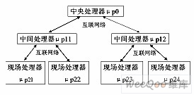
Figure 1 Common multi-microprocessor structure
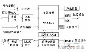
3.1 Main processor and its peripheral modules The main processor part adopts MOTOLORA's 32-bit microcontroller MC68332, which is a modular single-chip microcomputer with excellent data processing capability and powerful peripheral subsystem, mainly including the following Several microprocessor modules: System Integration Module (SIM), Central Processing Unit (CPU32), Time Processing Unit, and Static RAM Module. At the same time, in order to further enhance the system's functions, the following parts are expanded: 1) data non-volatile memory; 2) watchdog circuit; 3) master-slave processor interconnect module; 4) real-time clock circuit.
3.2 Analog Acquisition Module The analog acquisition module mainly includes signal pre-conditioning circuit, range online conversion circuit and analog-to-digital conversion main circuit.
3.2.1 Signal pre-conditioning circuit The function of the signal pre-conditioning circuit is to convert different ranges of voltage and current signals into voltage signals of the range required by analog switches and analog-to-digital converters. For the different signals, the corresponding pre-conditioning circuit must be used. Here, the current-type transformer is used for the AC voltage and current signal conditioning parts; the DC voltage conditioning circuit uses the optical isolation amplifier circuit with negative feedback; DC current The Hall sensor is used for conditioning, and for the convenience of adjustment, the output of the Hall sensor is divided by a resistor, and then amplified by two stages and then sent to the A/D converter.
3.2.2 Range Online Conversion Circuit In the communication power supply monitoring system, the level of the signal is very different due to the complexity of the signals to be processed. Therefore, how to realize the online conversion of the measurement range has always been a concern of people. The usual conversion method is to use a programmable gain amplifier, or a multi-input form, which is necessarily at the expense of increased circuit complexity and reduced reliability. In this system, the digital potentiometer X9241 is used to realize the online conversion of the measurement range. XICOR's X9241 integrates four non-volatile E2POTs. Each of the E2POTs contains 63 resistor units, a wiper count register (WCR) and four 8-bit data registers that can be read and written by the user. The contents of the wiper count register are used to control the position of the wiper in the resistor array and to perform bidirectional data transfer with the data registers. The specific communication protocol and timing can be found in reference [3]. Since the MC68332 does not have an I2C interface component, the interconnection with the X9241 is inconvenient. However, through timing analysis, it is found that the function of the I2C bus can be simulated by a general-purpose I/O bus and a timer, that is, two ports of the processor are used as the SDA and SCL buses, respectively, and the required clock is generated by an internal timer. The specific circuit connection circuit is shown in Figure 3.
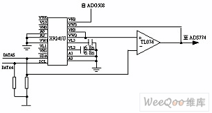 Figure 3 Measurement range online conversion circuit In theory, the digital potentiometer can be used to achieve any range conversion. However, due to the limitation of the accuracy of the analog-to-digital converter and the high real-time requirements of the communication power supply monitoring system, selecting too many conversion points will result in half the effect. Through experiments, it is only necessary to ensure that the input signal is near the 2/3 range of the analog-to-digital converter with only 1:1, 1:2, 1:5, 1:10, 1:20, and 1:50 ranges. Therefore, the two-way data conversion function between the sliding end counting register and the data register is skillfully utilized here to realize the above-mentioned six ranges of online conversion. The specific implementation method is: the storage value is 01H in the R0 of the two E2POTs. Since the sliding end counting register is automatically loaded into the value of R0 during the power-on reset, the amplifier is a follower when initializing, and the measurement is weak when needed. When the current is current, the value obtained from the initial acquisition is compared with a preset reference value, and an appropriate range is selected to be amplified and then re-acquired.
 After adopting this technology, the accuracy of data acquisition has been greatly improved. At the same time, however, this circuit sometimes oscillates at the output, causing distortion of the output waveform. The solution is to connect two resistors in series with the input and feedback terminals of the amplifier to increase the attenuation channel to the input.
3.2.3 Analog-to-digital conversion main circuit In the analog-to-digital conversion part, according to the requirements of system sampling accuracy and speed, we use AD company's high-speed analog-to-digital conversion ADS774. It is a low-power, high-sampling 12-bit A/D converter using CMOS technology. The analog input is 8.5us from the end of the conversion, the sampling frequency is up to 117khz, and it has an internal sample and hold circuit. It is itself a complete data acquisition system. The specific working sequence and working principle of ADS774 can be found in the literature [3], and will not be described here.
3.3 The correctness of the switching of the switch quantity acquisition module directly affects the accuracy of the control. As the switching quantity acquisition circuit in the communication power monitoring system must meet several requirements: First, the access of the acquisition circuit can not interfere with the working state of the original power supply device; second, the acquisition circuit is not allowed to be misread, otherwise it will cause the monitoring system Mis-control; Third, the switch quantity should meet the interface requirements of the monitoring system. The low level is 0~1V and the high level is 3.6~5V. This requires the acquisition circuit to have high reliability and isolation [4]. Figure 4 shows the conditioning circuit of the switching quantity acquisition circuit.
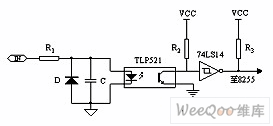 Figure 4 switching signal acquisition circuit
 3.4 Human Interface Module The human interface module includes a keyboard and a display module. Since the system is positioned unattended, the requirements for keyboard functions are relatively weak, so we adopted a 4*4 determinant keyboard. The display module uses the LCM19264A liquid crystal display module with built-in HD61202 control chip, which can display Chinese characters in four rows and twelve columns.
3.5 Communication Module The lower computer acts as a direct device-oriented slave and needs to communicate with the host computer remotely. At the same time, the lower computer also serves as the host to communicate with various intelligent devices. Therefore, in this system, RS232 and RS485 communication modes are adopted at the same time. Among them, the lower computer and the upper computer communicate with the host computer through the PSTN network to complete the functions of acquiring parameters, transmitting data, remote alarms, etc. Communication between intelligent devices is obtained through RS485 networking and its status [5].
The communication module uses a separate microprocessor DS80C320, which also defines a second function for the P1 port based on the ordinary single-chip microcomputer, thus having four full-duplex serial communication ports, six external interrupts, three timings/ The counter, which is also compatible with the 8051 on the command, is very suitable for the communication unit of the monitoring system.
3.5.1 Communication between the lower computer and the upper computer The communication medium between the lower computer and the upper computer adopts the PSTN network. In this system, a standard full-featured RS232 communication port is extended, and the external MODEM is connected to the PSTN network. The method is to achieve communication between the lower computer and the upper computer. Its implementation circuit is shown in Figure 5:
 Figure 5 DS80C320 and MODEM hardware interface diagram The 8251 is a universal synchronous/asynchronous transceiver with independent receiver and transmitter. It can be programmed to communicate in simplex and half-duplex mode. At the same time, it also provides a number of control signals required to connect with the MODEM, which can easily realize the interconnection with the MODEM.
 3.5.2 Communication between the lower computer and the intelligent device The master-slave networking mode of RS485 communication between the lower computer and the smart device is adopted. RS485 adopts balanced transmission and differential reception to realize communication. It has strong anti-common mode interference capability, and its transmission distance can reach 1.2 kilometers at a transmission rate of 10Kbps. The specific implementation scheme is shown in Figure 6.
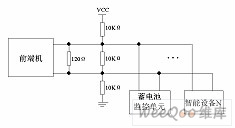 Figure 6 Overall implementation of RS485 communication
 3.6 The output circuit of the control quantity output module control quantity is shown in Figure 7. In the figure, OUT is the switching quantity control signal output by the processor, which is isolated from the external two-stage optocoupler and relay. Since the drive coil of the relay has a certain inductance, a large voltage may be generated at the moment of turn-off, so an absorption diode is connected in anti-parallel at both ends of the relay coil.
 Figure 7 Control quantity output circuit Figure 3.7 Sound and light alarm module When the system has an abnormal situation, the lower computer sends an alarm message to the upper computer through the remote communication network, and simultaneously controls the buzzer and the LED through two pieces of 8155 timers for local operation. Audible alarm. The specific implementation circuit is shown in Figure 8.
 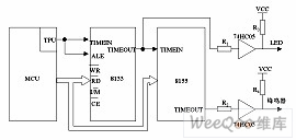 Figure 8 Sound and light alarm principle circuit diagram
 3.8 Auxiliary Power Module The communication power monitoring system, as the detection and control module of the communication power system, must have high reliability. Therefore, its auxiliary power module is usually supplied by the battery.
The system has a variety of different power requirements: +5V for microprocessor core voltage; -5V for partial op amp bias voltage; ±12V for analog to digital converter voltage, isolation +5V for Provides communication interface voltage; -8V adjustable voltage is used to provide LCD bias. The following multi-supply power supply scheme is proposed: an isolated DC/DC is used to obtain the system main power and then the system main power source uses a plurality of non-isolated DC/DC circuits to obtain various power sources. Since the auxiliary power supply is relatively low in the system except for the main power supply and most of them do not need to be isolated from the main power supply, the application of this scheme can conveniently realize the multi-output low-power power supply.
A circuit for generating a +5V main power source from a battery (voltage range 35V to -75V) is shown in FIG. The remaining power supplies can be implemented by a simple DC-DC converter from this main power supply: -5V bias: available from the MAX660 reverse-voltage charge pump (maximum current 100mA); ±12V voltage: from the MAX743 (internal integrated one liter Gain type and a back pressure type DC-DC converter with an output power of up to 3W). Isolated +5V: A low power isolation voltage can be obtained from the MAX845. The specific circuit above can be found in the MAXIM product brochure.
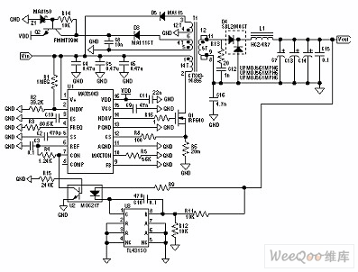 Figure 9 48V input, +5V output main power
 4 Experimental results and conclusions Take the DC voltage and AC voltage (take A-phase AC input as an example) signal test results as an example, and the test results are shown in Tables 1 and 2.

Table 1 DC voltage signal test results Table 2 AC voltage signal test results It can be seen from the experimental results that this set uses microprocessor and peripheral modules, analog acquisition module, switch acquisition module, control output module, man-machine The communication module monitoring system of the interface module, the sound and light alarm module and the communication module as the hardware circuit unit can fully meet the requirements in the "Technical Requirements for Centralized Monitoring System of Communication Power Supply and Air Conditioning". This product has been successfully developed and put into use. Practice has proved that the system has the advantages of high acquisition precision, low cost and easy upgrade, and is very suitable for the local communication power supply system which is quite popular at present.
LED Underwater light,Full colour underwater luminaires,Waterproof lighting underwater lamp
Kindwin Technology (H.K.) Limited , https://www.ktl-led.com