"The advantages of FPGAs combined with real-time signal processing can help speed up testing. At the same time, the flexibility of FPGA programming can quickly respond to the testing needs of new protocols." - Chun Zhang, InsTItute of Microelectronics, Tsinghua University
challenge:
Intricate UHF technology (including various standards and protocols) and RF parameter measurement make RFID products incompatible with each other, and bring huge testing challenges.
solution:
Using virtual instrumentation technology with digital signal processing technology, and finally based on NI's Software Defined Radio (SDR), a universal multi-protocol UHF RFID test platform was created. This platform is suitable for real-time testing of all RFID standards while supporting the custom features of the new protocol.
Radio Frequency Identification (RFID) is an automatic identification technology that has been introduced by many major manufacturers and standardization organizations for a wide range of standards and protocols for the UHF band. But because UHF technology is quite complex, there are still many problems, such as dazzling standards and protocols, and intricate RF parameter measurements. These problems can cause RFID products to be incompatible with each other while supporting the custom features of the new protocol. Therefore, it is necessary to build a universal test platform that is compatible with all standards, and reduce the test cost for RFID manufacturers.
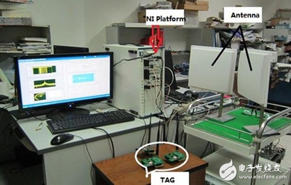
The operating principle of the RFID system The complete RFID system consists of RWs, tags and other peripheral modules. The RW identification results for the tags are shared with the computer via the network and stored in the database for inquiries.
Figure 1 shows the operating principle of the RFID system. When the system is operating, RW encodes and modulates the data to be transmitted on a carrier of a specific frequency, and then transmits it through an antenna to generate an electromagnetic field. For longer distance communications, backscattering is primarily used for UHF, which in turn transfers energy between the RW and the tag.
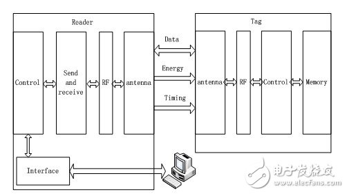
Figure 1. How the standard RFID system works
Once the tag enters the EM's electromagnetic field range, its circuitry demodulates the command signal from the RW, decodes the command data, processes the data, activates the transmit circuit as directed by the controller, and encodes the specific response data to the feedforward carrier. The feedforward carrier is backscattered to RW. The RW collects the response signal by receiving the antenna, provides the signal to the processing unit at the receiving end for demodulation and decoding, then checks the data and performs the magnetic field length analysis. Finally, the tag information will be transmitted to the database of the upper computer and stored for later reference.
Experimental Principles As RFID requirements such as communication speed and data read speed continue to increase, the communication timing specifications between tags and readers in RFID systems have also reached centimeters. A wide variety of RFID protocols create ambiguities between associated modulation/demodulation parameters, encoding/decoding methods, anti-impact algorithms, instructions and corresponding framework architectures, and indicator sets. Test systems built with traditional instruments will require real-time frequency spectrum analyzers, vector signal generators, vector network analyzers, and other components to generate excitation vectors for testing. In addition, a communication channel for the component under test (UUT) needs to be established, and the reflected signals of these components are collected in the RFID system. The current test system can perform related test and analysis operations based on a portion of the physical parameters of the RFID protocol. However, this system cannot provide timing to meet the protocol requirements, nor can it perform tests that meet the requirements of the protocol, nor can it support multiple protocol standards.
The SDR architecture's test system allows users to easily set up their own test system to meet changing test needs and provide a better man-machine interface (HMI). Due to the flexibility and scalability of the virtual instrument, the system can meet the upgrade needs of various applications without having to replace the hardware. In this way, the system itself can handle a variety of emerging communication protocols, which is the best choice for RFID system design.
Hardware Platform for RFID Test Systems This test system uses NI modular equipment. The NI PXIe-5641R RIO IF transceiver plus the NI PXI-5610 signal generator form an RF signal transmitter that converts the baseband signal to an RF signal (Figure 2). Embedded controllers can coordinate different templates, as well as some non-instant event action projects. The PXI bus on the back panel of the chassis transfers data at high speed between different boards.
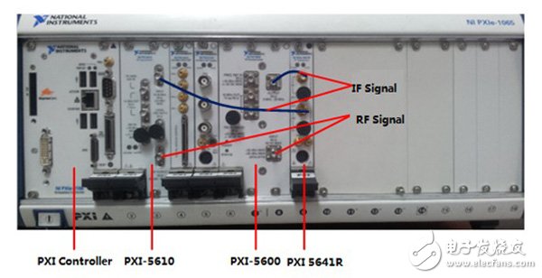
Figure 2. Hardware component description
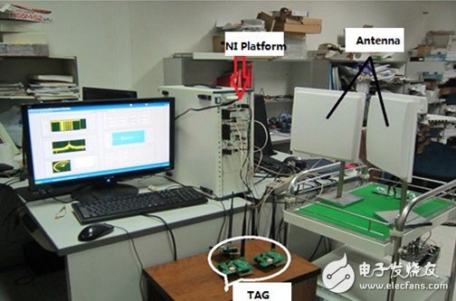
Figure 3. Hardware connection of the test system
One of the main functions of this test system is to use a general-purpose FPGA as a baseband processor instead of a vector signal generator and a vector signal analyzer in a conventional system. The advantages of FPGAs combined with real-time signal processing help increase test speed. At the same time, the flexibility of FPGA programming can quickly respond to the testing needs of the new protocol.
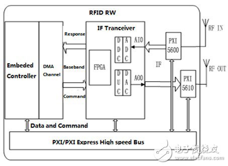
Figure 4. RFID system architecture using virtual instruments
As shown in Figure 4, the interface between the controller and the FPGA is primarily used to execute responses, instructions, and certain protocol parameters. The main function of the FPGA is to establish the signal and analyze the immediate acceptance and feedback of the signal, including the physical transceiver channel. The RF board provides the tag to be tested to the RF interface and provides the IF transceiver to the IF signal interface.
Hierarchical Distribution of System Functions The test system is divided into two levels: the FPGA platform and the host platform (as shown in the diagram). The host computer platform is responsible for controlling hardware, managing test processes, handling non-instant signals and using interfaces. The FPGA platform contains the physical transmission and reception routes, as well as the interface to the host computer.
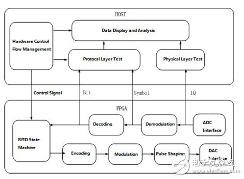
Figure 5. Software architecture and data flow
If you want to design a host platform, you must consider the coordination between different modules and user interface operations. In order to meet a wide variety of standards and protocol projects, the test system reads specific data files to implement all types of protocol instructions. As long as the data of the instruction document is modified, the user can customize the protocol content.
Figure 6 shows the user interface of the test system. All functions and analysis results of the test system are directly displayed on this interface.
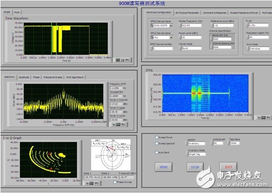
Figure 6. User interface
The system can test custom protocols with the 18000-6C protocol and can also set all parameters. Figure 7 shows the FPGA platform architecture.
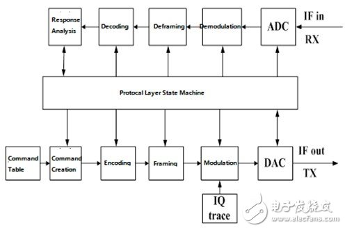
Figure 7. Block diagram of the FPGA platform
Test results The conformance test of the label protocol can be further divided into single label test, multi-label test and RF parameter test. The single tag test is mainly used to verify the RW operation of the tag and whether the switching of different tag states is correct. The multi-label test verifies the protocol's recoil algorithm and the efficiency of multi-tag identification.
All test results indicate that the test system is generally in good working condition and that each functional index meets the requirements. This system performs conformance testing and physical parameter testing against ISO18000-6C and a variety of custom protocols. The test distance is up to 3 meters, the transmission power is 20dBm, and the receiving resolution is -10dBm.
Pv Branch Connector,Mc4 Y Type Connector,Mc4 Branch,Mc4 Branch Adapter
Sowell Electric CO., LTD. , https://www.sowellsolar.com