With the rapid development of wireless communication technology, modulation methods with higher spectrum utilization have been widely used, such as PSK and QAM modulation. A common feature of these modulated signals is that the average value of the signal power and the envelope peak are different, and the peak-to-average ratio (ie, the peak factor Crest Factor) is large, which requires the amplifier to have good linear characteristics, otherwise nonlinear effects such as mutual Tuning the distortion will cause the spectrum to regenerate, which will cause adjacent channel interference. When designing amplifiers, such as WCDMA multi-carrier power amplifiers, linearization techniques are used to compensate for the nonlinearity of the amplifiers, thereby improving the spectral purity of the amplifier output signals and reducing adjacent channel interference. At the same time, we must also take into account the efficiency of the amplifier.
Linearization techniques are mainly divided into the following categories, as shown in Figure 1. In the design of the amplifier, several linearization techniques are generally used together to achieve the best linearization effect.
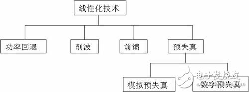
Digital predistortion is a kind of predistortion technology, and its basic principle is shown in Figure 2. Depending on the nonlinearity of the amplifier (amplitude and phase distortion), the signal from the input amplifier is inversely distorted, and the combination of two nonlinear distortion functions enables a highly linear, distortion-free system. Predistortion processing on a digital baseband is digital predistortion; predistortion processing on an analog circuit is analog predistortion.

The advantages of digital pre-distortion technology are: it works on digital baseband, low cost, and adaptability. It can also offset high-order intermodulation distortion by increasing the sampling rate and increasing the quantization order. A simple and efficient class AB amplifier can be used. Avoiding the complexity, high cost and high power consumption of feedforward technology, significantly improving the linearity and overall efficiency of the amplifier. The premise of using digital predistortion technology is that the nonlinear characteristics of the amplifier must be accurately measured, so that the input baseband signal can be predistorted according to the nonlinear characteristics of the amplifier.
However, due to the increasing signal bandwidth of wireless communication systems, such as WCDMA four-carrier bandwidth has reached 20MHz, with traditional narrow-band network measurement methods (such as vector network analyzer), it is impossible to accurately measure the non-bandwidth of the broadband amplifier under actual working conditions. Linear characteristics. Because the signal input to the amplifier when measured with a vector network analyzer is a swept signal, rather than a complex modulated signal of wideband in actual operation. This puts new demands on the nonlinear test of the amplifier.
Rohde & Schwarz uses the actual signal measuring amplifier method to use the digital signal source RS SMU200A or RS SMIQ, RS AMIQ to generate the actual working signal of the amplifier, which can be a broadband complex modulation signal or any other signal; The precision signal analyzer RS ​​FSQ or the spectrum analyzer RS ​​FSU, RS FSP measure the amplified signal to determine the AM/AM and AM/PM characteristics of the amplifier, ie determine the nonlinear characteristics of the amplifier, and provide the test signal accordingly. Digital pre-distortion function. The measurement method is controlled by Rohde & Schwarz's free test software RS AmpTune to control the instrument and process the data, which is verified to accurately measure the nonlinear characteristics of the amplifiers used in various communication standards and achieve significant linearity. The effect is saved, saving a lot of time and cost.
Basic test principleThe nonlinear characteristics of the amplifier are generally expressed in AM/AM and AM/PM. AM/AM refers to the characteristic that the output level varies with the input level, which represents the amplitude nonlinearity of the amplifier; AM/PM refers to the characteristic that the phase difference between the input and the output varies with the input level, representing the phase nonlinearity of the amplifier. It should be noted that AM/AM and AM/PM can only approximate the nonlinearity of the amplifier due to the memory effect of the amplifier, and the AM/AM and AM/PM characteristics measured at the input of the actual signal more accurately reflect the amplifier. The overall nonlinear characteristics including the nonlinearity caused by the memory effect. The key to this test method is to accurately measure the AM/AM and AM/PM characteristics of the amplifier when inputting the actual working signal, and to implement the digital pre-distortion function accordingly.
Hardware connectionThe hardware connection of the test scheme is relatively simple. The following uses the digital signal source RS SMU200A and the signal analyzer RS ​​FSQ as test instruments. The test architecture and connection are shown in Figure 3. The digital signal source RS SMU200A is used to generate arbitrary waveforms. Measured amplifiers for different communication standards, such as WCDMA, CDMA2000, WLAN, etc., can be tested using any standard arbitrary waveform (edited by the free software RS WinIQSim standard signal), or can generate band-limited noise or traditional double The tone signal is used for testing. The signal analyzer RS ​​FSQ is used to analyze the amplified signal through the amplifier. Run the test software RS AmpTune on a PC with a GPIB interface card to control the test instrument and process the data.
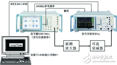
To ensure measurement accuracy, the signal analyzer uses the 10 MHz reference frequency of the source and uses the external trigger signal from the source. When connecting the amplifier, be aware that if the amplified RF signal is greater than 30dBm (ie the maximum allowable input level of the signal analyzer or spectrum analyzer), an attenuator must be added between the amplifier and the signal analyzer RS ​​FSQ to protect it. Signal analyzer.
Test software RS AmpTuneThe interface of the test software RS AmpTune is shown in Figure 4. The processing of the signal can be clearly seen from the interface of RS AmpTune: the digitized IQ signal in the signal source is subjected to I/Q modulation and up-conversion after D/A conversion and low-pass filtering, and the RF signal is fed into the amplifier. After the RF signal is amplified, it is input into the signal analyzer. The signal analyzer appropriately down-converts the input signal to obtain an intermediate frequency signal, and the intermediate frequency signal is digitally down-converted to obtain a digital IQ signal. The test software RS AmpTune analyzes the AM/AM and AM/PM characteristics of the amplifier by comparing the signal source and the IQ signal finally obtained by the signal analyzer.
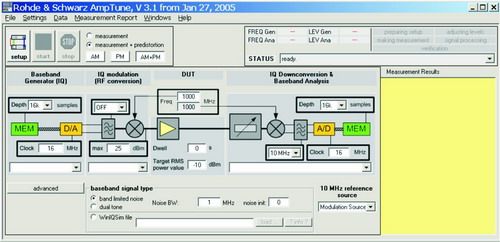
If you select "measurement" in the test software RS AmpTune, you can perform AM/AM and AM/PM measurements; if you select "measurement + predistorTIon", you can use any of the AM/AM and AM/PM immediately after measuring The waveform is digitally predistorted and then directly observed for digital predistortion. The software can perform AM/AM (amplitude) digital pre-distortion and AM/PM (phase) digital pre-distortion processing separately or simultaneously. Of course, we can also perform digital predistortion processing on any signal based on the measured AM/AM and AM/PM results. This provides great convenience for amplifier design.
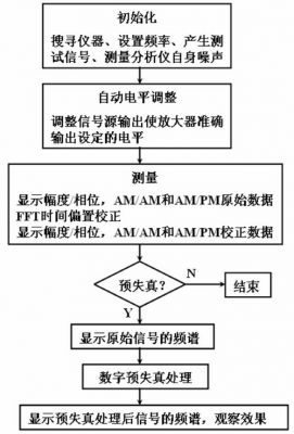
Testing processThe RS Amptune test process can be described by a simplified flow chart, as shown in Figure 5. In the second step, the “automatic level adjustment†step, the test software adjusts the output power of the signal source three times according to the “Target RMS power value†value set by the user, and finally makes the signal level of the amplifier output reach the set value. , its accuracy is as high as 0.1dB. In the third step, the "Measurement" step, "FFT Time Offset Correction" is used to correct the time offset of the residual after the external trigger is used. Because the external trigger signal can greatly improve the synchronization of signal generation and measurement (ie, time correlation), but the external trigger signal will be slightly time-biased after transmission through the BNC coaxial cable. If it is not corrected, it will still The measurement results have a serious impact. In the pre-distortion step, we can visually observe the optimization effect of the adjacent channel power ratio (ACPR) of the signal before and after pre-distortion.
Measurement results before and after time correction
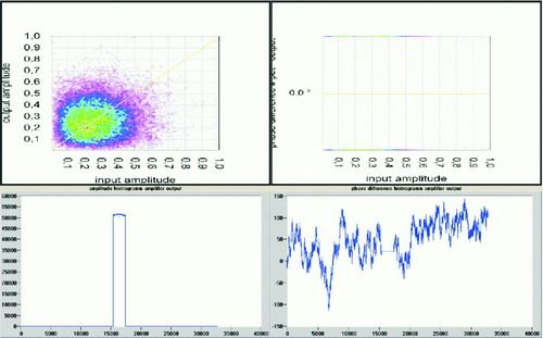
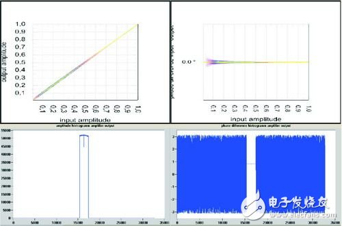
In the above “measurement†step, the test software will display the amplitude and phase measurement results before and after the time correction, respectively, and the user can determine whether the time correction is successful, as shown in Figures 6 and 7 below. This shows the importance of time correction.
Final measurement results of AM/AM, AM/PM
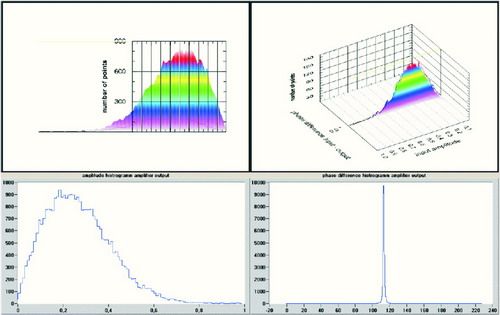
After the "Measurement" step is completed, the test software displays the final measurement results for AM/AM and AM/PM, as shown in Figure 8.
Measurement results before and after digital pre-distortion
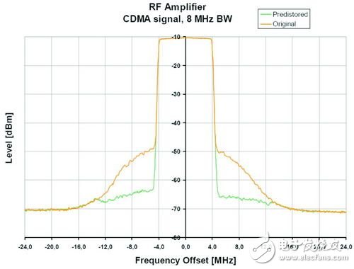
From Figure 9 and Table 1, the significant effect of digital predistortion on increasing adjacent channel power ratio (ACPR) can be clearly observed.
ConclusionWith the in-depth application of digital predistortion technology, corresponding digital predistortion chips have also been put on the market. These chips can be used to construct a digital predistortion amplifier that can monitor the output RF signal in real time and perform dynamic predistortion adjustment on the baseband. Because the test method described in this article is more accurate, it can be used to detect the predistortion effect of such digital predistortion chips.
In the design and test of the amplifier, we can use other sources such as RS SMIQ and RS AMIQ instead of RS SMU200A according to the actual situation; or use other spectrum analyzers such as RS FSU and RS FSP instead of RS FSQ. Get accurate test results and satisfactory digital pre-distortion effects.
Wired Earphones,Earphone With Mic,Wired Earbuds With Mic,In Ear Stereo Earphone
Guangzhou YISON Electron Technology Co., Limited , https://www.yisonearphone.com