Multi-beam antennas enhance wireless communication capabilities with enhanced spectral efficiency and higher quality of service. One of the methods of designing such an antenna involves spatial division multiple access (SDMA) techniques. The SDMA method provides higher user capacity without any significant technical changes in the limited spectrum.
Many wireless service providers use SDMA technology to optimize the available spectrum, which is typically limited to three intervals in the 360deg. coverage area. However, with a multi-beam antenna system, the coverage area can be increased to as many as 48. Because the system's beamforming network can reuse the available frequency and reduce the interference, it can serve more users and have better quality of service for the wireless network service area.
The system can transmit data, voice and video signals over long distances in multiple directions without the need for a relay station. In this way, the operating costs of the network are minimized and the reliability, quality and number of users are significantly improved. Replace short-range (low-gain) omnidirectional antennas with long-range (high-gain) narrow-beam directional antennas. In general, long-distance antennas increase the number of users in a single direction, but do not allow users in other directions to use the system. The proposed system solves this problem by using a multi-beam technique that can simultaneously and sequentially reuse high-gain narrow-beam antennas. This technology effectively achieves spherical coverage of omnidirectional antennas and significantly increases the number of users in all directions. . The frequency reuse technique can further increase the capacity.
The multi-beam system is based on a phased array antenna and a hardware solution for the OpTIbeam proprietary beamforming network developed by ElectromagineTIc Technologies Industries. Because the hardware solution does not require software programming and external power supply, it is suitable for harsh environments.
The main components of the multibeam antenna system discussed are antennas and beamforming networks. The antenna contains small antenna elements such as dipoles or patch antennas that are combined into an array. The beamformer provides the required signal phase for all antenna patches to generate beams in all directions. Multi-beam antenna systems To achieve the desired performance, the design parameters of both elements are critical.
The antennas employed within the systems discussed herein are based on patch antennas that make up the matrix. Patch antennas are based on proven microstrip high frequency printed circuit technology. The advantages of using a patch component in such a matrix arrangement are: small size, low manufacturing cost, light weight, ease of installation, and high reliability. The excitation of the different signal amplitudes and phases is fed to each patch depending on the desired direction of electromagnetic radiation. The different phases of the radiating components combine with the far field of the antenna to form a narrow beam. The antennas discussed herein are designed as linear phased array antenna systems in which the patches are equally spaced and employ progressive phase shifting techniques throughout the matrix.
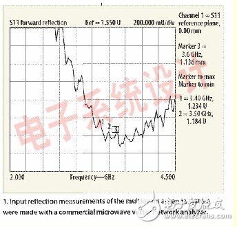
The spacing of each patch is maintained at half the center wavelength (λ/2). The centerline of the patch is initially selected as the feed point, but the actual exact position of the feed point is determined by empirical processing of the input reflection measurements with a high frequency vector network analyzer (VNA). In addition to the feed points, the shape of each patch was carefully selected to achieve a voltage standing wave ratio (VSWR) of less than 1.50:1 in the relevant frequency range. To improve performance over the frequency range of interest, the feed point is chosen to be slightly higher than the center point. Other design parameters of the patch antenna component include: resonant frequency = 3.7 GHz; substrate height = 0.030 inch; substrate dielectric constant = 2.2; patch antenna length = 1.575 inches; patch antenna width = 0.710 inches; feed point position slightly Above the center of the patch; polarization = vertical.
Many patch antennas linearly arrange patch elements on a single dielectric substrate to achieve an orientation beam width of 15 deg. and a vertical beam width of 7 deg., respectively. A four-beam antenna design requires a minimum of four patch antenna components. The four-beam system using this proposed technique is designed to have an antenna gain of 26 dB, a front-to-back ratio of more than 30 dB, and a sidelobe level of 20 dB (less than the main lobe level). The performance of a four-beam antenna design was measured using a commercial microwave VNA using a full sweep range of 2.0 to 4.5 GHz. The results are shown in Figure 1. The antenna system has a working range of 3.2 to 4.2 GHz and a VSWR of less than 1.50:1.
Beamformer designA beamformer is a complex network of passive microwave devices. It is used to provide the required phase and amplitude between the antenna and the system transceiver. The beamforming network forms a beam from the antenna matrix and controls the beam direction in an electronically controlled manner that does not require mechanical motion. Such an electronically controlled beamforming network can be designed by employing time or frequency domain analysis of antenna elements and associated electrical components. For the multi-beam antenna system discussed, frequency domain analysis is used in designing beamforming networks for broadband applications.
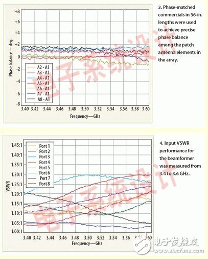
To minimize RF signal loss and maintain signal properties such as phase and amplitude, the beamforming network is typically placed next to the antenna assembly or integrated into the antenna assembly. In this example, the beamformer is placed next to the antenna and the phase matching cable is used to match the phase of the jumper matrix (see Figure 2). These phase matching cables provide a phase matching accuracy of ±1 deg. in the desired frequency band range. The insertion loss per 36-inch cable length contributes less than 0.5 dB.
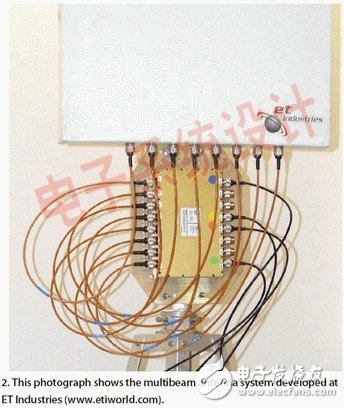
In this example, the beamformer was designed using a combination of orthogonal couplers, microwave mixing, and phase shifters to achieve phase requirements for four beams in the 60deg. A fully symmetric 90deg. hybrid joint can be utilized to achieve vector addition to generate the expected phase weight. The mixing can be integrated into the assembly by virtue of its inherent impedance conversion capability and by minimizing the use of matching converters to reduce overall insertion loss.
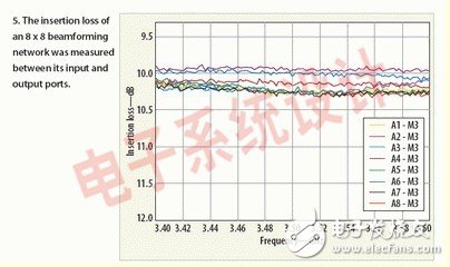
To demonstrate this design approach, a four-beam antenna beamformer for the 3.4 to 3.6 GHz band was designed. The performance was measured with Agilent Technologies' N5230A vector network analyzer. The N5230A was connected to the U3042A multi-port test set, also from Agilent, which also operated in the 3.4 to 3.6 GHz range. Figures 3, 4 and 5 show the results of a typical eight-beam beamforming network based on this design approach.
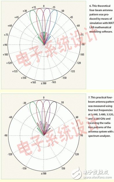
The radiation pattern of the multi-beam antenna system was measured in an open environment in the 3.4 to 3.6 GHz band. A beam-matcher and antenna are connected using a phase-matched RF cable. The input port of the beamformer is connected to four different center frequencies of 3.440, 3.480, 3.520, and 3.580 GHz, and the bandwidth of each channel is 7 MHz. The RF power used for the test was +5 dBm, and the combined received power from the antenna and beamformer was measured using a spectrum analyzer at a distance of 200 m. The power of the received signal is measured every 1.0 deg. on a circumference with a radius of 200 m, with four antennas as the center of the circle. Figure 7 shows the actual radiation pattern. Figure 6 also shows the theoretical radiation pattern simulated using MATLAB software.
Based on the analysis of the four-beam antenna system, it is possible to use six such antenna systems to provide full 360deg. wireless communication coverage. Potential applications for multi-beam antenna technology are Worldwide Interoperability for Microwave Access (WiMAX) and cellular networks. This approach can greatly increase the user capacity and spectral efficiency of such communication networks.
SDMA-based multi-beam antenna systems such as those discussed herein can greatly increase the capacity and throughput of a communication network through frequency reuse. The design methodology is simple and clear and its performance is verified in an outdoor environment with commercial test equipment. The measured results agree well with the results from the MATLAB software simulation.
Liquid Cooling Servo Motors,Cnc Router Servo Motor,Metal Milling Servo Motor,Ac Spindle Servo Motor
Zhejiang Synmot Electrical Technology Co., Ltd , https://www.synmot-electrical.com