Since the satellite communication system shares the frequency band with the microwave relay system, co-channel interference occurs. In order to avoid harmful interference to the microwave relay system around the earth station after the completion of the new satellite earth station, according to the Ministry of Information Industry of the People's Republic of China Order No. 21 "establishing satellite communication network and setting up the use of earth stations management regulations" [2002.6.21] And the “Provisional Regulations for the Construction of Satellite Communication Networks and the Use of Earth Stations†[National No Management (1995.1) No. 4] requires the station-building units to provide accurate data while reporting relevant technical data before the satellite earth station determines the site. The argument should be sufficient, and the analysis of the interference analysis of the satellite earth station to the microwave relay station should be made clear. The radio management department shall use the proposed electromagnetic environment test report and interference analysis report of the proposed site as the technical reference for the approval of the site. This paper mainly introduces the calculation steps and specific methods of the interference of the satellite earth station to the microwave relay station around the satellite earth station (centered on the satellite earth station antenna) within a radius of 100 km, for your reference.
1. Relevant technical standardsAccording to the provisions of GB13616-92 "Electromagnetic Environmental Protection Requirements for Microwave Relay Stations", the interference allowable value of the uplink signal of the satellite earth station to the microwave relay communication system is -
(1) For the relative zero-level point of any channel of the 2500 km hypothetical reference circuit of the analog microwave relay communication system, the interference power shall meet the following requirements:
a. For more than 20% of any month, the noise meter weighted 1 minute average power does not exceed 1000 pW.
b. The noise meter weighted 1 minute average power does not exceed 50,000 pW in any month over 0.01%.
(2) For the 64 kbit/s output of the 2500 km hypothetical reference digital path of the digital microwave relay communication system, the interference power should meet the following requirements:
a. In any time 0.04% or more of any month, the average bit error rate caused by any one minute of RF interference power should not exceed 10-6.
b. The average bit error rate caused by any one second of RF interference power shall not exceed 10-3 in any period of 0.0054% or more.
c. The accumulated error time of the error caused by the RF interference power in any month should not exceed 0.032%.
2. Calculation of relevant parametersIn the actual interference analysis calculation, the latitude and longitude of the pre-selected satellite earth station site and the latitude and longitude of the submarine point of the geostationary satellite and the latitude and longitude of the station of the microwave relay station (hereinafter referred to as the microwave station) are known, through these known parameters. It can be calculated: the azimuth and elevation angle of the satellite earth station, the distance between the satellite earth station and the microwave station, the space loss of the satellite earth station and the microwave station, the satellite earth station discrimination angle, the microwave station discrimination angle, and the satellite earth station antenna Gain, microwave station antenna gain, actual interference signal level value, interference signal allowable value (interference tolerance value).
2.1 Earth station communication azimuth and elevation calculation
It is assumed that the latitude and longitude of the satellite earth station A are φ1 and θ1, the latitude and longitude of the sub-satellite point S of the geostationary satellite W are Ψ and 0, and φ0=Ψ-φ1 is the longitude difference of the satellite point S to the satellite earth station A, and the microwave station B The latitude and longitude of the points are φ2 and θ2, respectively.
When the satellite earth station A antenna is aligned with the satellite W, its elevation angle EL and azimuth angle AZ are:


For geostationary satellites,
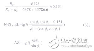
Where, RE is the radius of the Earth, 6378 km; hE is the distance of the satellite from the ground is about 35786.6 km.
Note: There is a positive or negative azimuth. This formula is based on Zhengnan. China is basically based on the north, so:
![]()
2.2 Calculation of communication azimuth and path between satellite earth station and microwave station
It is known that the latitude and longitude of two points A and B of the satellite earth station and the microwave station can be calculated as follows.
2.2.1 Calculate the true north angle from point A to point B
The true north angle AZ from point A to point B is calculated by the following formula:
![]()
When tgAZ "0", θ1 "θ2, the azimuth angle is AZ;
If θ1 θ2, the azimuth angle is π+AZ;
When tgAZ "0, θ1" θ2, the azimuth is π-|AZ|;
If θ1 "θ, the azimuth is 2π-|AZ|.
Where: φ1 is the longitude of point A, radians; φ2 is the longitude of point B, radians;
Θ1 is the latitude of A point, radians; θ2 is the latitude of B point, radians.
2.2.2 Calculate the distance from point A to point B
1 Large circle path calculation method
d = cos-1 (cosαcosβ + sinαsinβcosC)*α (7).
Where C=ψ2-ψ1; θ1, θ2, ψ2 and ψ1 are as defined above.
2 Flat ground calculation method (d "10 km")
![]()
Where R is the radius of the Earth, which is 6378 km; θ1, θ2, ψ2 and ψ1 are as defined above.
2.3 Calculation of interference discrimination angles for satellite earth stations and microwave stations
The angle between the communication direction of the satellite earth station communication direction and the interference direction AB of the microwave station is ψ, that is, the interference discrimination angle of the communication direction of the satellite earth station to the microwave station. φA is the angle between the projection of the satellite communication direction in its communication azimuth and the horizontal direction of the satellite earth station to the microwave station. CB is perpendicular to AB, and point C is projected to the ground at point O (see Figure 1).
It can be seen from Figure 2:
φA'=|AZ-AZ'| ( rad ) ,
φA = φA' 0 ≤ φA' ≤ π,
Or φA=2π-φA' φA'>π.
2.3.1 Calculation of the interference discrimination angle of the satellite earth station communication direction to the interference direction of the microwave station

It can be seen from Fig. 1 that ψ = cos-1 (cosEL* cosφA) (9).
(The above calculation assumes that the microwave station works at an elevation angle ε = 0) If ε ≠0, then the formula (9) should be written as follows:
ψ = cos-1 (cos ε * cos EL * cos φ A + sin ε * sinEL) (10).
2.3.2 Calculation of the discrimination angle of the microwave station communication direction to the interference direction of the satellite earth station
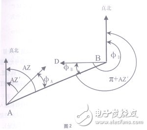
It can be seen from Figure 2:
φB'=|φD-AZ'+π| ( rad ) ,
φB = φB' 0 ≤ φB' ≤ π;
Or φB = 2π - φB' φB' > π.
In Fig. 2, BD is a useful signal transmission path, AB is an interference signal transmission path, and φD is a microwave station communication direction.
2.4 Determination of antenna gain
The antenna gain is determined by the actual antenna pattern. When the antenna pattern data is missing, the gain of the antenna in a certain direction can be calculated by the following formula.
Let D be the antenna diameter (m); λ be the wavelength (m); when D/λ is 100,
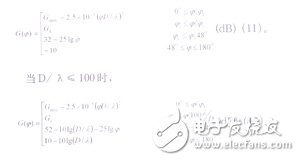
Where: Gmax—the antenna main lobe gain dB, Gmax=10 lg [0.6 (πD/λ) 2], 0.6 is the antenna efficiency;
G1—the first sidelobe gain of the antenna is dB, G1=2+15 lg (D/λ);
Ψ—the angle of departure from the central axis of the main beam, degrees;
ψ1—Half of the half-power angular width of the main lobe can be expressed by:

2.5 Calculation of transmission loss
2.5.1 Line-of-sight path transmission loss calculation
Line-of-sight path transmission loss mainly includes free space transmission loss and absorption loss of oxygen and water vapor:
Lsd = Lo + (γ0 + γw)d (13).
Lo = 92.5 + 20 lgf + 20 lgd (14).
Where: Ls - line of sight path transmission loss, dB;
Lo—free space transmission loss, dB;
f - frequency, GHz; d - path length, km;
Γ0—oxygen absorption attenuation coefficient, dB/km;
Γw—water vapor absorption attenuation coefficient, dB/km.
When f<15 GHz, γW=0, then
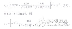
Where: Ï - water vapor concentration, depending on the radio climate zone.
2.5.2 Over-the-horizon path transmission loss calculation
The over-the-horizon propagation mechanism is mainly diffraction (including obstacle diffraction and smooth spherical diffraction) and tropospheric scattering. For transmission paths that are slightly more than the line of sight, diffraction is the main propagation mechanism in most cases, and the scattering is negligible; for paths far beyond the line of sight, scattering is the main propagation mechanism, and diffraction is negligible; For medium-length paths between the two, both propagation mechanisms need to be considered. Consider the parameters: HC - path clearance, m; HO - free space clearance, m. There are four main propagation losses:
(1) Smooth spherical diffraction loss.
(2) Diffraction loss on irregular terrain obstacles.
One or more obstacles are often encountered in the propagation path, and in order to estimate the additional diffraction loss of these obstacles, the shape of the obstacle is usually idealized. When the thickness of the obstacle is relatively narrow, it can be regarded as a blade-shaped obstacle; when the thickness of the obstacle is relatively wide and the top is relatively flat, it can be regarded as a circular obstacle. Therefore, it can be subdivided into the calculation of the 1-edge diffraction loss; 2 the calculation of the diffraction loss of a single circular obstacle.
(3) Calculation of multiple obstacle diffraction.
(4) Tropospheric scatter propagation.
The above four kinds of propagation loss are more complicated to calculate. Because they are limited by the space, they will not be described in detail here. For details, see "Interference Calculation Method for Microwave Relay Communication System" (GB/T 13619-92).
2.5.3 Calculation of transmission loss Lsd for different types of paths
(1) When the path clearance HC>HO, and the path distance does not exceed 100 km, Lsd is calculated according to the free space transmission loss:
Lsd = Lo = 92.5 + 20 lgf + 20 lgd (17).
(2) When the path clearance HC ≤ HO, and the path distance does not exceed 100 km, Lsd is calculated according to the free space transmission loss and the diffraction transmission loss is added:
Lsd=Lo+Ld (18).
3. Calculation of the actual interference signal level value and the interference signal allowable value (interference tolerance) at the input end of the microwave receiver3.1 Calculation of the actual interference signal level value
The actual interference signal level value is calculated as:
I=PI-LI+GI+GR-LR-Lsd-XPD+K (19).
Where, I-interference signal power at the input of the microwave receiver, dBm;
PI-interference signal output power of the transmitter, dBm;
GI—the antenna gain of the satellite earth station antenna in the direction of the interfering station, dBi;
GR—the antenna gain of the microwave antenna in the direction of the interfered source, dBi;
LR—receiver feeder system loss, dB;
LI—interference station transmitter feed line system loss, dB;
Lsd—path transmission loss, dB;
XPD—cross polarization decoupling, dB; (can be omitted due to little impact)
Signal bandwidth
K—bandwidth correction factor, K=10lg ———— .
Interference bandwidth
3.2 Calculation of interference signal allowable value (interference tolerance value)
3.2.1 Calculation of the allowable value (interference tolerance value) of the interference signal of the analog microwave station
The calculation of the allowable values ​​of the interference signals of the analog TV/FM system and the FDM/FM system is complicated, and it is necessary to calculate the carrier-to-noise ratio when the useful signal and the interference signal are respectively low, medium and high modulation indices. This article describes two relatively simple calculation methods commonly used in engineering.
A. The microwave receiver input of the FM system with the FM system is used to estimate the interference level of the satellite earth station from the same frequency band using the FDM/FM/FDMA system using the following formula (for site selection).
1. For more than 20% of any month, the allowable value of the interference signal level is:
I0=10lgTR-176.6 (any 4 kHz bandwidth) (20).
2. For any month over 0.01%, the allowable interference level is:
I0=10lgTR-159.6 (any 4 kHz bandwidth) (21).
Where: I0—the allowable value of the interference signal at the input of the microwave receiver, dBW;
TR—the noise temperature of the microwave receiver, K.
For the noise temperature TR, the following equation can be used:
TR = (F-1) & TImes; 290 (22).
Where: F - the noise figure of the microwave receiver.
B. Estimate the interference signal allowable value (interference tolerance value) by the threshold deterioration amount. The threshold level refers to the received signal level that just satisfies the outage probability indicator. One way to describe the degradation of the threshold is to give the maximum interference signal allowed value. Equation (23) can be used to estimate the maximum interference signal allowable value for TV/FM systems and FDM/FM systems. The formula (23) is expressed as follows:
I0=Rth-10+Se (23).
Where: I0—the maximum interference signal allowed value dBm;
Rth - the threshold value of the interfered microwave receiver, dBm;
Se—Intermittent microwave receiver effective selectivity, dB.
3.2.2 Calculation of the allowable value (interference tolerance value) of the interference signal of the digital microwave station
A. It is known from the calculation formula of the error rate of the interference allowable value:
1MPSK modulation system
Pe≈0.5exp(Eb/N0)=0.5expC/N (DBPSK);
When M=2, Pe≈0.5erfc(X) (BPSK);
Pe≈erfc[XSin(t)] (MPSK) when M>2.
Where erfc(Y)—the residual error function, can be expressed by:
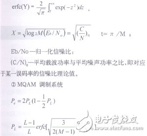
(C/N) 0—the ratio of the average carrier power to the average noise power, ie the theoretical value of the signal to noise ratio corresponding to a certain bit error rate;
Baseband signal error rate of one of two orthogonal components of the PL-MQAM modulation system;
M—the number of modulation levels;
L = √M.
B. Calculation of actual threshold SNR
The theoretical value (C/N) of the signal-to-noise ratio can be calculated according to the formula in 3.2.2 A. In addition, the deterioration caused by equipment imperfection, the deterioration caused by internal disturbance of the system and the deterioration caused by external disturbance of the system; therefore, the actual The threshold SNR can be expressed as follows:
(C/N)th = (C/N)0 + δ1 + δ2 + δ3 (24).
Where: (C/N)th—the threshold SNR value corresponding to a certain bit error rate (such as 10-3 or 10-6), dB;
(C/N)0—the theoretical value of the signal-to-noise ratio corresponding to a certain bit error rate (such as 10-3 or 10-6), dB;
Δ1—the amount of equipment deterioration (given by the equipment manufacturer), dB;
Δ2—the amount of deterioration of internal interference of the system, dB;
Δ3—the amount of deterioration of external disturbances in the system, dB.
C. Signal interference ratio allowed value calculation
The signal-to-interference ratio can be approximated by the following formula:
(C/I) 0 = (C/N)th + Δ (dB) (25).
Where: Δ—the signal-to-interference ratio, dB, due to external system interference.
Δ has the following relationship with δ3:
Δ=-10lg (100.1δ3-1),
Usually δ3=0.04~0.4 dB, then Δ=10~20 dB.
D. Calculation of interference signal allowable value (interference tolerance value)
I0=C-(C/I)0 (26).
Where: I0—interference signal allowable value;
C—threshold reception level;
(C/I)0—The theoretical value of the signal-to-noise ratio corresponding to a certain bit error rate (such as 10-3 or 10-6), dB.
4. Comparison of actual interference signal level and interference signal allowable value (interference tolerance) at the input of microwave receiverAfter calculation, the value (dBm) of the actual interference signal power I at the input of the microwave receiver and the allowable value of the interference signal I0 (dBm) (interference tolerance value) can be obtained.
When there is a microwave station I≥I0 around the satellite earth station, the satellite earth station cannot be set up at the proposed site, and the satellite earth station will interfere with the microwave relay station operating within 100 km of the same frequency band.
When I<I0, a satellite earth station can be set up at the proposed site, and the satellite earth station will not interfere with the microwave relay station operating within 100 km of the same frequency band.
5. ConclusionThe electromagnetic environment test and interference analysis of the satellite earth station is a very important work before the construction of the satellite earth station. Doing this work carefully can improve the utilization of radio spectrum resources, effectively avoiding the interference that uplink signals may cause to the microwave stations in the same frequency band after the completion of the satellite earth station, and reduce the cost of building satellite earth stations. In accordance with the requirements of the “Interim Regulationsâ€, this paper only gives the calculation method within a radius of 100 km around the satellite earth station (centered on the antenna of the satellite earth station). In the actual engineering design, it is necessary to carry out the calculation of the coordination area of ​​the transmitting satellite earth station, draw the coordination area map, and perform the interference calculation for all the microwave stations in the same frequency band in the coordination area, and finally determine which microwave stations and satellite earth in the coordination area. Harmful interference exists between stations, and it is best to avoid interference caused by newly built satellite earth stations to microwave stations in the same frequency band.
Solar Water Heater Controller,Smart Water Heater Control,Water Heater Control Panel,Solar Hot Water Controller
Full Industrial CO.,ltd. , https://www.iotaindustrial.com