Jitter measurement has always been called the highest level of oscilloscope test measurement. The most traditional method of jitter measurement is to use persistence to see the changes in the waveform. Later it evolved into a difficult problem in the probability of higher mathematics, and the problem of quasi-accurate jitter measurement results became more complicated.
The characteristics of the clock can be used to measure the stability of the frequency with a frequency meter, measure the phase noise with a spectrum analyzer, and measure the TIE jitter, period jitter, and cycle-cycle jitter with an oscilloscope. But what are the principles of the time domain measurement method and the frequency domain measurement method? How is the relationship between TIE jitter and phase noise jitter derived?
Jitter is an important measure of clock performance. Jitter is generally defined as the short-term offset of a signal relative to its ideal position at a particular time. This short-term offset is expressed in the time domain as jitter (the following jitter is specific to time domain jitter) and in the frequency domain is phase noise. This article focuses on the underlying clock jitter and phase noise as well as its measurement methods, and the relationship between the two.
1 Introduction to jitter
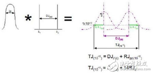
Jitter is a measure of the time domain signal and reflects how much the signal edge deviates from its ideal position. There are two main components of jitter: deterministic jitter and random jitter. Deterministic jitter is repeatable and predictable. Its peak-to-peak value is bounded. In general, DJ refers to its pk-pk value. Random jitter is an unpredictable timing noise. Gaussian distribution is generally used to approximate the analysis. In theory, the intermediate value can be infinitely large, so the random jitter has no peak-to-peak boundary. In the usual sense, the RJ index refers to its RMS value, and its value at a certain bit error rate can be estimated based on its RMS value. The most common analytical method currently used is the use of the Double Dirac model. The model assumes that the tails on both sides of the probability density function obey the Gaussian distribution, the Gaussian distribution is easy to simulate, and the lower probability distribution can be derived downward. The total jitter is the convolution of the RJ and DJ probability density functions.

However, the industry is still controversial about whether the Gaussian distribution can accurately depict the tail of a random jitter histogram. The true random jitter is Gaussian distribution, but in the actual measurement, multiple low-amplitude DJs are convoluted into a distribution function, which results in the measured probability density distribution centering close to the Gaussian distribution, while the tail is mixed with some DJs. . Therefore, the true RJ may only be part of the jitter of the Gaussian model, and the RJ may be amplified during the measurement, and the total jitter is also amplified.
2 jitter measurement
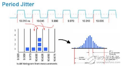
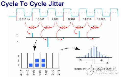
There are usually three measurement methods for clock jitter, which correspond to three jitter indicators: TIE (TIme Interval Error), period (cycle jitter), and Cycle-Cycle (adjacent period jitter).
TIE jitter (time interval error), taking the time difference between the measured clock edge and the ideal clock edge as the sample, that is, using the TIEn in the figure as a sample, by statistically analyzing many samples, the clock edge is deviated from the ideal clock edge. The change and distribution of values ​​are as shown in the following figure:

Period Jitter (sample jitter), which is a sample of the clock signal. The sample is sampled by Pn. The statistical analysis of many samples is used to characterize the change and distribution of the clock signal period Pn. It makes sense to establish a hold time specification. As shown below:

Cycle-Cycle Jitter (Cycle-Cycle jitter), taking the difference between the adjacent periods of the clock signal as a sample, that is, taking Cn as a sample in the figure, and statistically analyzing a plurality of samples (1K~10K) to characterize the clock signal phase. The change and distribution of the change in the neighboring period are generally used in situations where it is necessary to limit the frequency mutation. As shown below:

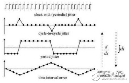
The relationship between the three jitter indicators of TIE, Jperiod and Jcycle-cycle is as follows:
The differentiation of the TIE can result in periodic jitter.

Where Δtpn is the period jitter, tn is the actual period, T0 is the ideal period, and ΔtIEn is the TIE jitter.
The differential of the period jitter can be obtained by cycle-cycle jitter.
![]()
Where Δtcn is the period jitter, tn is the actual period, and Δtpn is the period jitter.
The relationship between the three can be represented by the following figure:

3 phase noise introduction
The phase noise reflects the spectral purity of the single-carrier signal. If there is no phase noise, all the power of the signal should be concentrated at its oscillation frequency f0 (left carrier, left). This ideal signal is represented by Asin(ωt). Due to the presence of phase noise (left Noise in the figure below), a Φ(t) phase signal is modulated on the ideal signal, and the entire signal is represented as Asin(ωt+Φ(t)). In the spectrum, a part of the power is extended to the adjacent frequency to form a sideband (bottom right). The phase noise is defined as the logarithm of the ratio of the power Pn to the total signal power Ps in a 1 Hz bandwidth at a given offset frequency fn of a single sideband, ie 10 lg (Pn/Ps), and the phase noise is in dBc/Hz@fn. To represent. Here, the meaning of dBc is the ratio of the power of a certain frequency to the total power of the signal (right in the figure below), which corresponds to the ratio of the clock phase offset to the clock period.

Gear reduction motor is a component of a gear reducer and a motor. This type of component is also commonly referred to as a gearbox motor or a geared motor. It is usually assembled and assembled by a professional reducer manufacturer.
Gear reduction motors are widely used in automatic mechanical equipment, especially in packaging machinery, printing machinery, corrugated machinery, color box machinery, conveying machinery, food machinery, three-dimensional parking equipment, automatic storage, three-dimensional warehouse, chemical, textile, dyeing and finishing equipment, etc. Micro gear reduction motors are also widely used in the fields of electronic locks, optical equipment, precision instruments and financial equipment.
Gear reduction motor,Reduction motor,Speed reducer motor,12 volt gear reduction motor,Gear reduction box electric motor,12v gear reduction motor
Shenzhen Maintex Intelligent Control Co., Ltd. , https://www.maintexmotor.com